GL541操作手册.pdf - 第16页
Part 1 1 – 4 V ersion 2.0 Chapter 1 Outline of the Machine GL-541E Operation

Part 1
1 – 3
Version 2.0
Chapter 1 Outline of the Machine
(9) Empty
(10) Empty
(11) MP Board HIMV-924A
This board outputs signals to the VME bus, and contains a slot for a
memory card.
1.3.2 CPU Module (Board Loader PLC)
The CPU module (board loader PLC) controls the in-conveyor, main conveyor,
and out-conveyor.
1.3.3 Direct I/O Controller
The direct I/O controller, as its name implies, controls all input and output
signals directly.
GL-541E Operation

Part 1
1 – 4
Version 2.0
Chapter 1 Outline of the Machine
GL-541E Operation
Chapter 2 Before Operating the Machine
Part 1
2. Before Operating the Machine
2.1. Turning On the Power Supply
Turn on the circuit breaker on the door at the bottom front of the machine.
Press the POWER ON button on the GL-541E operation panel to turn on the machine.
Note: The machine memory contents have to be cleared when the ROM chips are replaced to
upgrade the software or when the machine operates abnormally. The memory contents
are cleared by turning on the machine power supply while holding down the RESET
button. This is known as the reset-start operation.
All status data, Proper data and programs are deleted from the GL-541E memory when
the reset-start operation is carried out. Therefore, this data has to be transmitted to the
machine from F4G after the machine power supply has been turned back on. The display
following a reset-start is shown at the top of the following page.
1
2
3
4
56
7
8
9
G
#
–
F
1
2
3
4
✽
B
S
C
R
0
↑
←
↓
→
POWER
OFF
CYCLE
STOP
POWER
ON
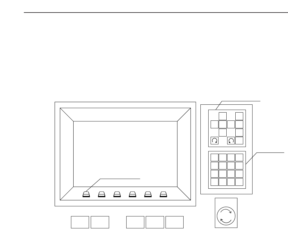
START RESET
Inching Keys
Numerical
Keypad
Emergency
Stop
Function Keys
1 – 5
Version 2.0 GL-541E Operation