GL541操作手册.pdf - 第49页
Part 2 2 – 16 V ersion 2.0 Chapter 2 Glue Check Function 2.2 Creating Programs Procedure: (1) Enter the glue check information in the [Mark Edit] window in the Program Editor. Type: Select “G” (Glue Check Mark) from the …
Chapter 2 Glue Check Function
Part 2
2. Glue Check Function
The glue check function uses the CCD camera that reads fiducial marks to measure the
diameter and area of glue check dots applied to a board and then compares these measured
values to the reference values stored in the machine. The results are used for feedback control
of the glue application pressure to ensure that the glue volume applied is consistent.
2.1 Necessary Conditions for Use of the Glue Check Function
In order to use the glue check function there are certain conditions that the boards and
glue must meet.
• The glue must have an evenly distributed color.
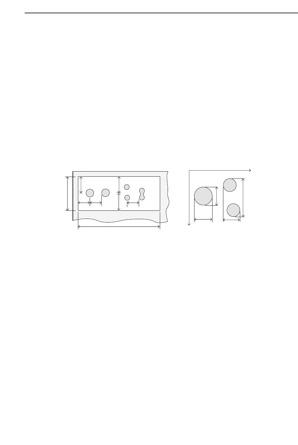
• The boards must have a glue check dot area which meets the conditions shown in
the left diagram below.
a and b are the distances from the center of a glue check dot (camera field of vision) to
the edge of another glue check dot or to the edge of the glue check dot area.
In addition, x1, y1, x2, and y2 are the reference measurements in the X and Y directions; a
and b must also comply with the following conditions.
a > y1 x (1+G_check_limit/100)
a > y2 x (1+G_check_limit/100)
b > x1 x (1+G_check_limit/100)
b > x2 x (1+G_check_limit/100)
Note: The G_check_limit is defined in Proper data. Accordingly, the dimensions A and B
must be sufficient to satisfy the a and b size requirements for every glue check dot.
• The background color of the glue check dot area (copper film, solder plating, white
paint, etc.) must provide sufficient contrast with the color of the glue to be
distinguishable by the camera.
A
B
a
b
Y+
X+
y1 y2
x1
x2
a
a
bb
2 – 15
GL-541E Operation
Version 2.0
Part 2
2 – 16
Version 2.0
Chapter 2 Glue Check Function
2.2 Creating Programs
Procedure:
(1) Enter the glue check information in the [Mark Edit] window in the Program Editor.
Type:
Select “G” (Glue Check Mark) from the drop-down list box.
Pattern:
Input is not required.
Read Level:
Input is not required.
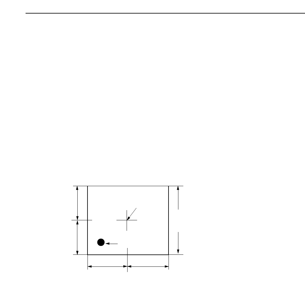
Scanning Level:
Specifies the area in which a search is made for the glue dot. The default value is
2.00 but a setting of about 4.00 is recommended. The unit is mm. Refer to the
following figure.
Size A, B, C:
Input is not required.
Size X, Y:
Input is not required.
Inspection Method:
Input is not required.
Mark Color:
Set the glue color as seen by the camera to black (Dark) or white (Bright).
Area specified in "Scan".
(Length of one side of a square)
Camera Center
Application Point
A
B
C
D
Note: A=B=C=D
GL-541E Operation
Part 2
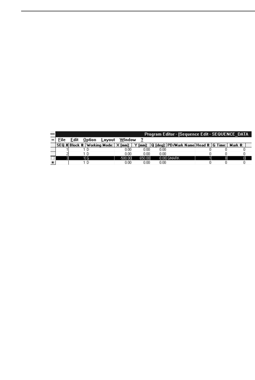
(2) Insert a glue check sequence in the sequence data.
To create a glue check sequence line, enter “G” in the “Working Mode” column of
the sequence data and then input the X and Y coordinates of the application point in
the glue check area (X and Y columns), the glue syringe number (“Head #” column),
and the glue application time (“G Time” column). In the “PD/Mark Name” column
input the name of the mark data file created in step (1) above.
Note: Any number of glue check sequences may appear at any position in the
program. However, for each syringe the glue application time (the value
entered in the “G Time” column) must be the same in every glue sequence.
Normally a “1” should be input in the “Block #” column. If a zero is input the
glue check will not be performed.
2 – 17
GL-541E Operation
Chapter 2 Glue Check Function
Version 2.0