GL541操作手册.pdf - 第25页
Chapter 3 Operation Panel Part 1 3.1.8 Selecting and Executing Commands Press the function keys F1 to F6 to execute the commands displayed on the CRT. Note: If an error occurs which causes an emergency stop, the function…

Part 1
1 – 12
3.1.3 Interrupting Auto Operation
CYCLE STOP button
If the CYCLE STOP button is pressed while the machine is operating in the
automatic mode, automatic operation stops after the current sequence is
completed and the system then waits for the START button to be pressed.
3.1.4 Cancelling the Board Wait Status
CYCLE STOP button
If the main conveyor enters the board wait mode during the loading cycle, this
mode can be cancelled by pressing the CYCLE STOP button.
3.1.5 Clearing Alarms
RESET button
The RESET button flashes when an alarm has occurred.
Press the RESET button to clear the alarm display and connect the 200 V power
supply.
3.1.6 Carrying out the Reset-Start Operation
RESET button + POWER ON button
The memory contents need to be cleared after the ROM chips are replaced, an OS
error occurs, or the axes move abnormally. Clear the machine memory (Proper,
status and program data will all be cleared) by turning off the machine power
and then turning it back on while holding down the RESET button.
This is known as the reset-start operation.
3.1.7 Stopping the Machine Instantaneously
EMERGENCY STOP button
The 200 V power supply to the machine is cut off when this button is pressed.
Press this button to stop the machine instantaneously in emergencies.
GL-541E OperationVersion 2.0
Chapter 3 Operation Panel
Chapter 3 Operation Panel
Part 1
3.1.8 Selecting and Executing Commands
Press the function keys F1 to F6 to execute the commands displayed on the CRT.
Note: If an error occurs which causes an emergency stop, the function keys displayed
on the initial display are disabled.
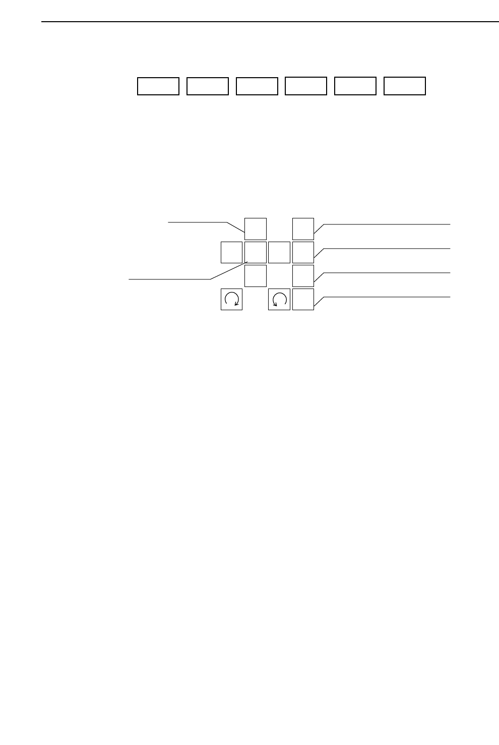
3.1.9 Moving Axes Manually (Inching)
The operator can elect to move the machine axes. This operation is called
inching. The GL-541E has four types of axes: X, Y, θ, and Z.
• Inching keys
Press an arrow key to carry out inching of the selected axis.
• Rapid inching key
Press this key and an inching key simultaneously to inch the axis at a rapid
rate.
• Inching axis selection keys
Inching can be carried out at any time except during machine operation or
Proper data measurement. However, only the axes selected by the inching
axis selection keys can be inched; it is not possible to inch all of the axes at
the same time.
The axes selected by each of the selection keys and the action of the inching
keys is described below.
1
2
3
4
F
↑
←
↓
→
Inching axis selection key 1
Inching axis selection key 2
Inching axis selection key 3
Inching axis selection key 4
Inching keys
Rapid inching key
F1 F2 F3
F4 F5 F6
1 – 13
GL-541E Operation
Version 2.0

Part 1
1 – 14
(1) Inching axis selection key 1 (X, Y, θ axes)
“X Y Q” is displayed in the first status area to indicate that these three axes
can be inched.
[ ↑ ] Y-axis, + direction [ ↓ ] Y-axis, – direction
[←] X-axis, + direction [→] X-axis, - direction
[] θ-axis, + direction [ ] θ-axis, – direction
(2) Inching axis selection key 2 (Z1, θ axes)
“Z1 Q” is displayed in the first status area to indicate that these axes can be
inched.
[ ↑ ] Z1-axis, up [ ↓ ] Z1-axis, down
[] θ-axis, + direction [ ] θ-axis, - direction
(3) Inching axis selection key 3 (Z2, θ axes)
“Z2 Q” is displayed in the first status area to indicate that these axes can be
inched.
[ ↑ ] Z2-axis, up [ ↓ ] Z2-axis, down
[] θ-axis, + direction [ ] θ-axis, - direction
(4) Inching axis selection key 4 (Z3, θ axes)
“Z3 Q” is displayed in the first status area to indicate that these axes can be
inched.
[ ↑ ] Z3-axis, up [ ↓ ] Z3-axis, down
[] θ-axis, + direction [ ] θ-axis, - direction
Note: To prevent collisions with the Z-axis, inching of the X and Y-axes is only
possible after zero setting is completed. Furthermore even after zero setting is
completed, if the Z-axis is at its lower limit, inching of the X and Y-axes is
impossible.
GL-541E OperationVersion 2.0
Chapter 3 Operation Panel