GL541操作手册.pdf - 第26页
Part 1 1 – 14 (1) Inching axis selection key 1 (X, Y, θ axes) “X Y Q” is displayed in the first status area to indicate that these three axes can be inched. [ ↑ ] Y-axis, + direction [ ↓ ] Y-axis, – direction [ ← ] X-axi…
Chapter 3 Operation Panel
Part 1
3.1.8 Selecting and Executing Commands
Press the function keys F1 to F6 to execute the commands displayed on the CRT.
Note: If an error occurs which causes an emergency stop, the function keys displayed
on the initial display are disabled.
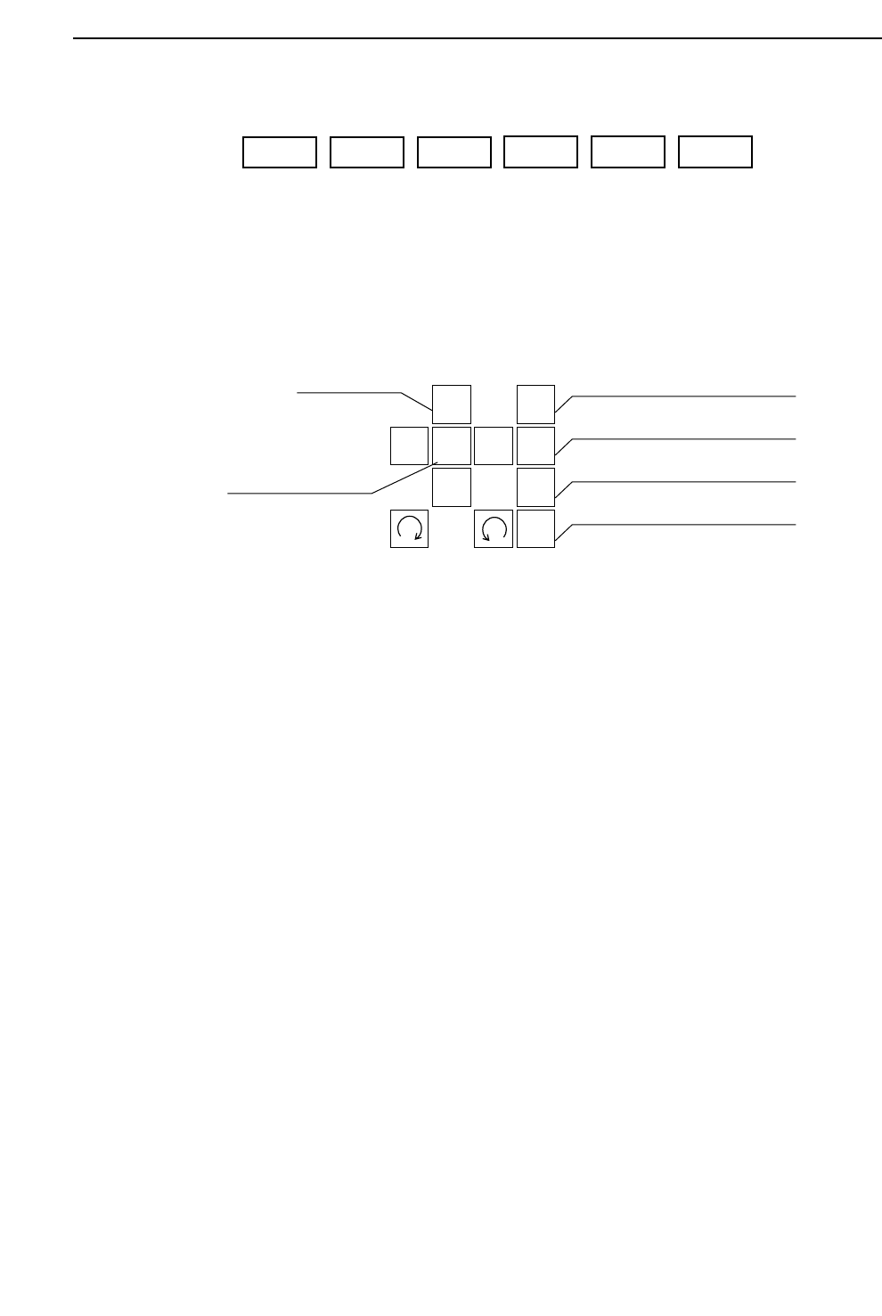
3.1.9 Moving Axes Manually (Inching)
The operator can elect to move the machine axes. This operation is called
inching. The GL-541E has four types of axes: X, Y, θ, and Z.
• Inching keys
Press an arrow key to carry out inching of the selected axis.
• Rapid inching key
Press this key and an inching key simultaneously to inch the axis at a rapid
rate.
• Inching axis selection keys
Inching can be carried out at any time except during machine operation or
Proper data measurement. However, only the axes selected by the inching
axis selection keys can be inched; it is not possible to inch all of the axes at
the same time.
The axes selected by each of the selection keys and the action of the inching
keys is described below.
1
2
3
4
F
↑
←
↓
→
Inching axis selection key 1
Inching axis selection key 2
Inching axis selection key 3
Inching axis selection key 4
Inching keys
Rapid inching key
F1 F2 F3
F4 F5 F6
1 – 13
GL-541E Operation
Version 2.0

Part 1
1 – 14
(1) Inching axis selection key 1 (X, Y, θ axes)
“X Y Q” is displayed in the first status area to indicate that these three axes
can be inched.
[ ↑ ] Y-axis, + direction [ ↓ ] Y-axis, – direction
[←] X-axis, + direction [→] X-axis, - direction
[] θ-axis, + direction [ ] θ-axis, – direction
(2) Inching axis selection key 2 (Z1, θ axes)
“Z1 Q” is displayed in the first status area to indicate that these axes can be
inched.
[ ↑ ] Z1-axis, up [ ↓ ] Z1-axis, down
[] θ-axis, + direction [ ] θ-axis, - direction
(3) Inching axis selection key 3 (Z2, θ axes)
“Z2 Q” is displayed in the first status area to indicate that these axes can be
inched.
[ ↑ ] Z2-axis, up [ ↓ ] Z2-axis, down
[] θ-axis, + direction [ ] θ-axis, - direction
(4) Inching axis selection key 4 (Z3, θ axes)
“Z3 Q” is displayed in the first status area to indicate that these axes can be
inched.
[ ↑ ] Z3-axis, up [ ↓ ] Z3-axis, down
[] θ-axis, + direction [ ] θ-axis, - direction
Note: To prevent collisions with the Z-axis, inching of the X and Y-axes is only
possible after zero setting is completed. Furthermore even after zero setting is
completed, if the Z-axis is at its lower limit, inching of the X and Y-axes is
impossible.
GL-541E OperationVersion 2.0
Chapter 3 Operation Panel

Part 1
3.1.10Displaying G Data Feedback Coefficients
Press inching axis selection key [2] while holding down the rapid inching key [F].
A table of G data feedback coefficients corrected at the machine is displayed.
Press key [2] while holding down the [F] key again and the coefficients are
expressed in milliseconds.
Press the [2] and [F] keys simultaneously once more to return to the original
display.
Note: When the table of G data feedback coefficients is displayed in milliseconds,
values can also be input in milliseconds.
The G data feedback coefficients are cleared when the machine power is turned
off or when a new program is selected. The G data feedback coefficients are used
as temporary data until the program is edited at F4G.
3.1.11 Turning the Glue Valve On
Press inching axis selection key [3] while holding down the rapid inching key [F]
in order to turn on the Z-axis side glue valves. The inching axis selection keys
[2], [3] and [4] can then be used to turn on a glue valve on the selected Z-axis
side.
“Z1 Q” is displayed in the first status area to indicate that this axis can be inched.
Press this key to turn on glue valve 1 (Z1).
“Z2 Q” is displayed in the first status area to indicate that this axis can be inched.
Press this key to turn on glue valve 2 (Z2).
“Z3 Q” is displayed in the first status area to indicate that this axis can be inched.
Press this key to turn on glue valve 3 (Z3).
1 – 15
GL-541E Operation
Version 2.0
Chapter 3 Operation Panel