GL541操作手册.pdf - 第47页
Part 2 2 – 14 V ersion 2.0 Chapter 1 Operation GL-541E Operation
Part 2
2 – 13
Version 2.0
Chapter 1 Operation
Thus the lower limit timer allots time for the glue to settle on the board. Normally
it is set to 0 seconds. Set the lower limit timer to between 10 and 20 milliseconds
to resolve this type of problem.
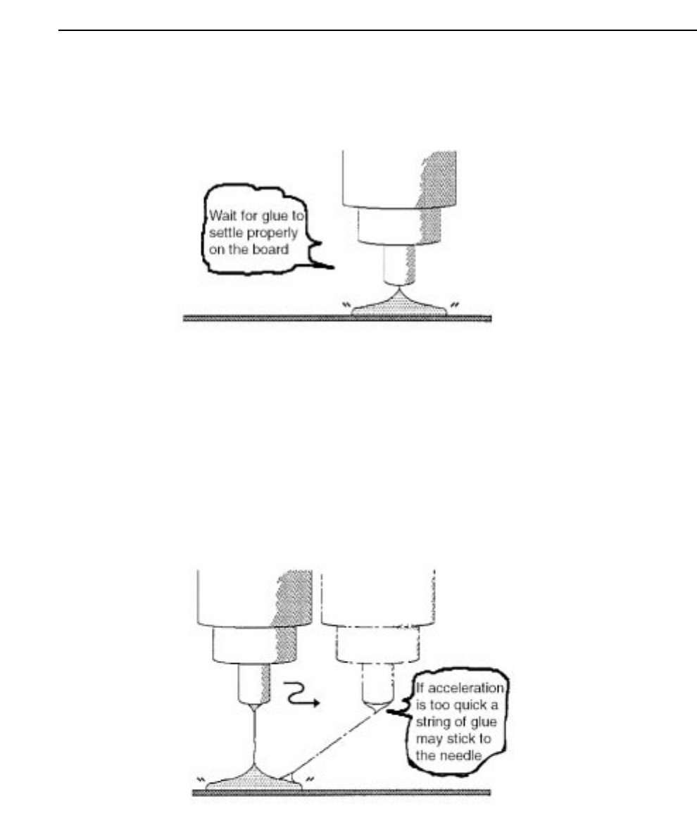
Glue easily becomes stringy:
After application is complete a string of glue may stick to the needle as it raises to
its upper limit. At times this glue may stay attached to the needle until the needle
descends to perform the next glue sequence, at which point the string will fall and
adhere to the board. The upper limit timer is used to prevent glue strings from
falling to the board. The upper limit timer dictates the time the needle takes to
move to the next dispensing point after reaching its upper limit. Thus the upper
limit timer allots time to allow for the glue string to contract back to the board.
Normally it is set to 0 seconds.
Note: The application cycle time increases only by as much as the timer settings are
lengthened.
GL-541E Operation

Part 2
2 – 14
Version 2.0
Chapter 1 Operation
GL-541E Operation
Chapter 2 Glue Check Function
Part 2
2. Glue Check Function
The glue check function uses the CCD camera that reads fiducial marks to measure the
diameter and area of glue check dots applied to a board and then compares these measured
values to the reference values stored in the machine. The results are used for feedback control
of the glue application pressure to ensure that the glue volume applied is consistent.
2.1 Necessary Conditions for Use of the Glue Check Function
In order to use the glue check function there are certain conditions that the boards and
glue must meet.
• The glue must have an evenly distributed color.
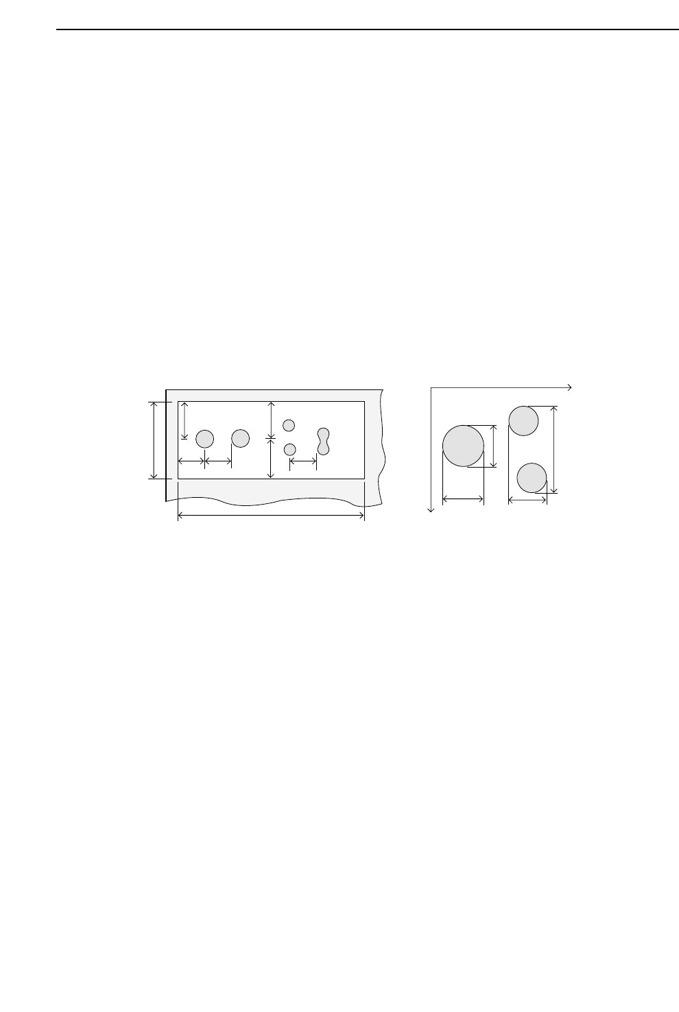
• The boards must have a glue check dot area which meets the conditions shown in
the left diagram below.
a and b are the distances from the center of a glue check dot (camera field of vision) to
the edge of another glue check dot or to the edge of the glue check dot area.
In addition, x1, y1, x2, and y2 are the reference measurements in the X and Y directions; a
and b must also comply with the following conditions.
a > y1 x (1+G_check_limit/100)
a > y2 x (1+G_check_limit/100)
b > x1 x (1+G_check_limit/100)
b > x2 x (1+G_check_limit/100)
Note: The G_check_limit is defined in Proper data. Accordingly, the dimensions A and B
must be sufficient to satisfy the a and b size requirements for every glue check dot.
• The background color of the glue check dot area (copper film, solder plating, white
paint, etc.) must provide sufficient contrast with the color of the glue to be
distinguishable by the camera.
A
B
a
b
Y+
X+
y1 y2
x1
x2
a
a
bb
2 – 15
GL-541E Operation
Version 2.0