GL541操作手册.pdf - 第50页
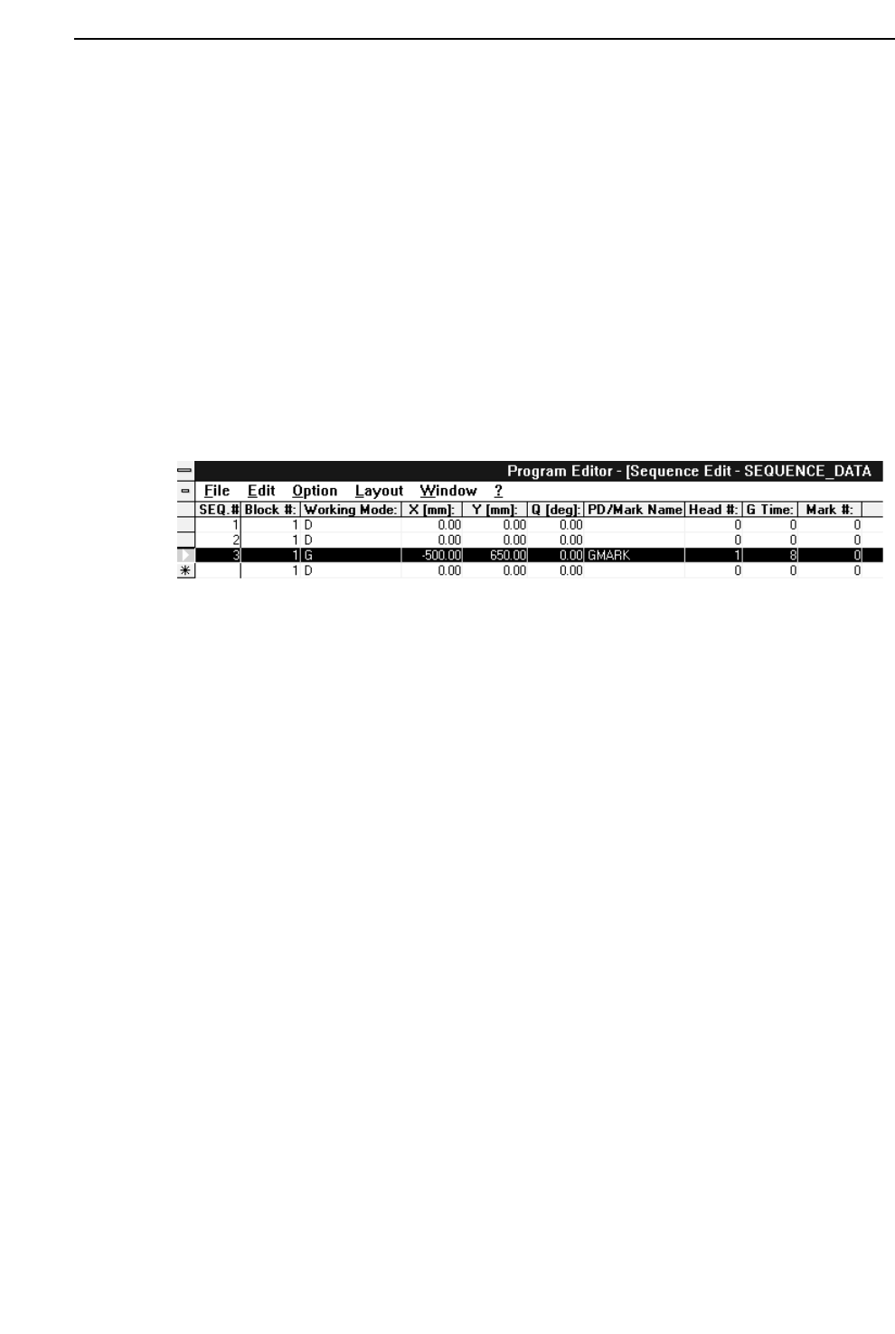
Part 2 (2) Insert a glue check sequence in the sequence data. To create a glue check sequence line, enter “G” in the “Working Mode” column of the sequence data and then input the X and Y coordinates of the application po…
Part 2
2 – 16
Version 2.0
Chapter 2 Glue Check Function
2.2 Creating Programs
Procedure:
(1) Enter the glue check information in the [Mark Edit] window in the Program Editor.
Type:
Select “G” (Glue Check Mark) from the drop-down list box.
Pattern:
Input is not required.
Read Level:
Input is not required.
Scanning Level:
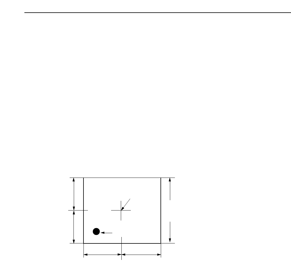
Specifies the area in which a search is made for the glue dot. The default value is
2.00 but a setting of about 4.00 is recommended. The unit is mm. Refer to the
following figure.
Size A, B, C:
Input is not required.
Size X, Y:
Input is not required.
Inspection Method:
Input is not required.
Mark Color:
Set the glue color as seen by the camera to black (Dark) or white (Bright).
Area specified in "Scan".
(Length of one side of a square)
Camera Center
Application Point
A
B
C
D
Note: A=B=C=D
GL-541E Operation
Part 2
(2) Insert a glue check sequence in the sequence data.
To create a glue check sequence line, enter “G” in the “Working Mode” column of
the sequence data and then input the X and Y coordinates of the application point in
the glue check area (X and Y columns), the glue syringe number (“Head #” column),
and the glue application time (“G Time” column). In the “PD/Mark Name” column
input the name of the mark data file created in step (1) above.
Note: Any number of glue check sequences may appear at any position in the
program. However, for each syringe the glue application time (the value
entered in the “G Time” column) must be the same in every glue sequence.
Normally a “1” should be input in the “Block #” column. If a zero is input the
glue check will not be performed.
2 – 17
GL-541E Operation
Chapter 2 Glue Check Function
Version 2.0

Part 2
2 – 18
2.3 Specifying Glue Check Proper Data
The following Proper data items are required for glue dot feedback control. (The values
listed below are examples only.)
131 : G_check_multi_Z1 (1 - 200) [%] = 100
132 : G_check_multi_Z2 (1 - 200) [%] = 100
133 : G_check_multi_Z3 (1 - 200) [%] = 100
134 : Glue_check_limit (1 - 200) [%] = 30
138 : Needle_Z1 (Single Twin) = Single
139 : Needle_Z2 (Single Twin) = Twin
140 : Needle_Z3 (Single Twin) = Twin
141 : Glue_area_Z1 (1 - 200) [um
2
/%] = 100
142 : Glue_area_Z2 (1 - 200) [um
2
/%] = 100
143 : Glue_area_Z3 (1 - 200) [um
2
/%] = 100
144 : Glue_check_delay (0 - 4999) = 2
131, 132, 133 G_check_multi_Z1, Z2, Z3 [%] feedback control coefficients
The feedback control coefficients determine the rate of feedback that is carried out at one
time.
Note: As there is not necessarily a one-to-one relationship between fluctuations in the glue
application pressure and fluctuations in the actual volume applied, 100% feedback may
result in overcompensation. For example, if the glue application pressure lies in a
suitable range, the next small feedback control may cause the pressure to move out of
this range thereby destabilizing the glue application volume. Furthermore, it may take a
long time for the situation to restabilize.
GL-541E Operation
Version 2.0
Chapter 2 Glue Check Function