GL541操作手册.pdf - 第28页
Part 1 1 – 16 3.1.12 T urning on the CCD Camera Lamps Press inching axis selection key [4] while holding down the rapid inching key [F] to turn on the camera lamps. Press the [4] and [F] keys simultaneously once more to …

Part 1
3.1.10Displaying G Data Feedback Coefficients
Press inching axis selection key [2] while holding down the rapid inching key [F].
A table of G data feedback coefficients corrected at the machine is displayed.
Press key [2] while holding down the [F] key again and the coefficients are
expressed in milliseconds.
Press the [2] and [F] keys simultaneously once more to return to the original
display.
Note: When the table of G data feedback coefficients is displayed in milliseconds,
values can also be input in milliseconds.
The G data feedback coefficients are cleared when the machine power is turned
off or when a new program is selected. The G data feedback coefficients are used
as temporary data until the program is edited at F4G.
3.1.11 Turning the Glue Valve On
Press inching axis selection key [3] while holding down the rapid inching key [F]
in order to turn on the Z-axis side glue valves. The inching axis selection keys
[2], [3] and [4] can then be used to turn on a glue valve on the selected Z-axis
side.
“Z1 Q” is displayed in the first status area to indicate that this axis can be inched.
Press this key to turn on glue valve 1 (Z1).
“Z2 Q” is displayed in the first status area to indicate that this axis can be inched.
Press this key to turn on glue valve 2 (Z2).
“Z3 Q” is displayed in the first status area to indicate that this axis can be inched.
Press this key to turn on glue valve 3 (Z3).
1 – 15
GL-541E Operation
Version 2.0
Chapter 3 Operation Panel
Part 1
1 – 16
3.1.12Turning on the CCD Camera Lamps
Press inching axis selection key [4] while holding down the rapid inching key [F]
to turn on the camera lamps.
Press the [4] and [F] keys simultaneously once more to turn the lamps off.
3.1.13Inputting Data
The numeric keypad is used to inch machine axes, execute special functions, and
input sequence numbers and feedback coefficient values.
• Numerical keys – [0] to [9]
Press these keys to input numbers.
• Backspace key (BS)
Press this key to delete values previously input.
The cursor moves one space to the left each time
this key is pressed.
• Carriage return key (CR)
Press this key after a number has been input to enter the value. If the
system is waiting for an entry, this input wait mode can be cleared by
pressing this key.
• G, # keys
Use the [G] and [#] keys to input G data feedback coefficients. These keys
can be used any time “Ready” is displayed in the lower left part of the
screen.
Example: Input the following to set data G7 to increase the amount of
glue applied by 10%:
G 7 # 1 1 0 [CR]
56
7
8
9
G
#
–
1
2
3
4
✽
B
S
C
R
0
GL-541E OperationVersion 2.0
Chapter 3 Operation Panel
Part 1
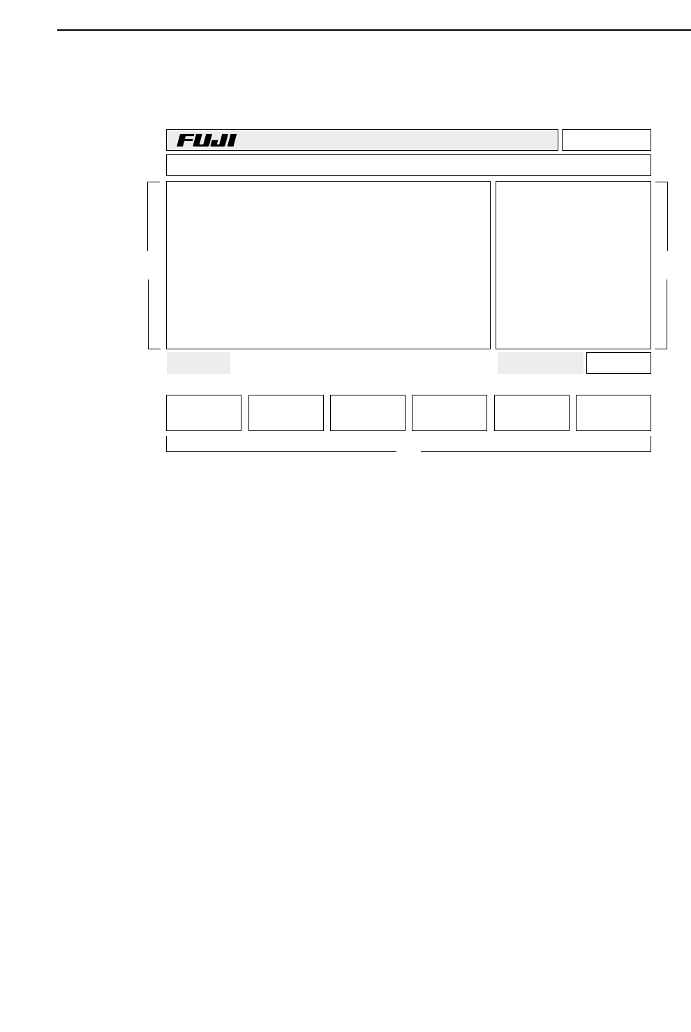
3.2 CRT Display
The CRT displays a number of machine conditions as well as the function keys and the
version number. The items displayed are explained below.
(a) Version No.
Displays the control system ROM version number.
(b) Line Mode
Displays the communication line mode.
(c) Production Program Name
Displays the name of the current production program.
(d) Quantity Completed
Displays the quantity of boards completed.
(e) Production Quantity
Displays the quantity of boards to be produced.
(f) First Status Area
Displays the current command status.
(g) First Display Area
Displays the current machine status.
Page 000
v2.10
Off line
TEST_GL Prod 00000 Sche 00000
AUTO STEP LOADER PROGRAM SET
Ready 0010B0403600 jog X Y Q
✴
PCB Loading
Status
Mode Product:
(a)
(b)
(c)
(d)
(e)
(f)
(g)
(h)
(i)
(k)
(l)
(j)
(m)
1 – 17
GL-541E Operation
Version 2.0
Chapter 3 Operation Panel