GL541操作手册.pdf - 第54页
Part 2 Example: Input 110 [CR] to increase the current diameter [um 2 ] by 10%. The corresponding area (in pixels) is added to the reference area (displayed as Ref.data in the display above). 2.5 Carrying Out Glue Dot Fe…
Part 2
2 – 20
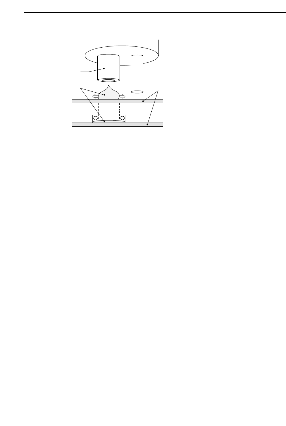
2.4 Reading the Glue Reference Diameter and Area
Procedure:
(1) Press the [SET] and [STATUS] function keys.
Press the [GLUCHK] function key to display G.ref.set in the first display area.
Note: Refer to Part 3, Chapter 3, Description of Commands, page 513-000, “Selecting
the Glue Check Mode”.
(2) Carry out the glue check sequence using step or automatic operation and stop when
the dispensed glue volume viewed by the camera is correct. The operator has to
look at the monitor and visually determine when the glue volume is correct. The
final measured diameter and area are then taken as the reference values.
(3) Leave the automatic operation mode. Press the [SET], [STATUS], and [GLUCHK]
function keys again to display “G.correct” in the first display area.
This mode permits the feedback conditions to be adjusted.
(4) To manually adjust the glue reference diameter and area, “G.ref [%]” will display in
the bottom left-hand corner of the screen. Using the numeric keypad, it is possible
to change the reference diameter. Use the following commands:
[SET] -> [MANUAL] -> [GLUE] -> [G ref. set] -> [Z1], [Z2] or [Z3]
Nozzle
Glue
Board
GL-541E Operation
Version 2.0
Chapter 2 Glue Check Function

Part 2
Example: Input 110 [CR] to increase the current diameter [um
2
] by 10%. The
corresponding area (in pixels) is added to the reference area (displayed as Ref.data in the
display above).
2.5 Carrying Out Glue Dot Feedback
2.5.1 Glue Dot Feedback Sequence
The GL-541E glue dot feedback procedure is carried out in the following order.
(1) Apply glue dots according to the set data.
(2) Acquire images of the glue dots with the CCD camera.
(3) Inspect the glue dots.
(4) Check the size of the glue dots.
(5) Check the area of the glue dots.
(6) Calculate the amount of feedback.
(7) Apply this feedback to the application air pressure.
FUJI v2.00
off_1 line
No.Prog Prod 0000 Sche 0000 Ref Set
Ref.data: 1500(vm2)
Set-up
Return
Ref [%]
2 – 21
GL-541E Operation
Chapter 2 Glue Check Function
Version 2.0
Part 2
2 – 22
2.5.2 Precautions
• The distance from the center of any glue check dot to the edge of any other
glue check dot must be farther apart than the distance from the center of the
reference dot to its outer limit as defined by the glue check limit.
In addition, patterns or dirt in this area which make it difficult to
distinguish the glue check dots may lead to erroneous readings. Refer to
Section 2.1, “Necessary Conditions for Use of the Glue Check Function”.
• In some cases the camera may not be able to see a glue dot because of light
reflection from the glue.
If the outline of the glue dot is visible but parts of the center are not, the area
of the dot is still calculated correctly.
2.5.3 Range where Feedback Control is Not Carried Out
• If the glue check limit set in the Proper data is exceeded (i.e. if the area or
diameter lies outside the limit) an error occurs.
• If the difference between the measured area and the reference area is within
5% (offset displays on the monitor), the dot size is considered to lie within
the range of permissible error and no feedback control is carried out.
Area calculated
correctly
GL-541E Operation
Version 2.0
Chapter 2 Glue Check Function