GL541操作手册.pdf - 第52页
Part 2 134 Glue check limit [%] Feedback control range This item provides a basis for evaluating whether the shape and area of the dispensed glue dots are correct or not. The diameter feedback range is calculated accordi…

Part 2
2 – 18
2.3 Specifying Glue Check Proper Data
The following Proper data items are required for glue dot feedback control. (The values
listed below are examples only.)
131 : G_check_multi_Z1 (1 - 200) [%] = 100
132 : G_check_multi_Z2 (1 - 200) [%] = 100
133 : G_check_multi_Z3 (1 - 200) [%] = 100
134 : Glue_check_limit (1 - 200) [%] = 30
138 : Needle_Z1 (Single Twin) = Single
139 : Needle_Z2 (Single Twin) = Twin
140 : Needle_Z3 (Single Twin) = Twin
141 : Glue_area_Z1 (1 - 200) [um
2
/%] = 100
142 : Glue_area_Z2 (1 - 200) [um
2
/%] = 100
143 : Glue_area_Z3 (1 - 200) [um
2
/%] = 100
144 : Glue_check_delay (0 - 4999) = 2
131, 132, 133 G_check_multi_Z1, Z2, Z3 [%] feedback control coefficients
The feedback control coefficients determine the rate of feedback that is carried out at one
time.
Note: As there is not necessarily a one-to-one relationship between fluctuations in the glue
application pressure and fluctuations in the actual volume applied, 100% feedback may
result in overcompensation. For example, if the glue application pressure lies in a
suitable range, the next small feedback control may cause the pressure to move out of
this range thereby destabilizing the glue application volume. Furthermore, it may take a
long time for the situation to restabilize.
GL-541E Operation
Version 2.0
Chapter 2 Glue Check Function

Part 2
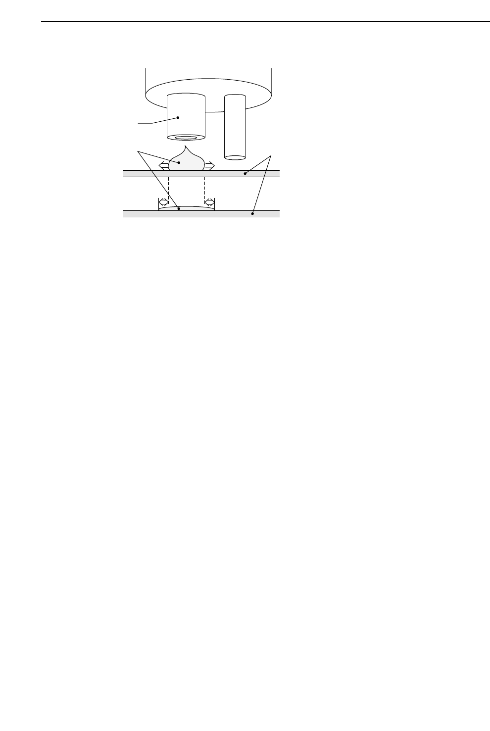
134 Glue check limit [%] Feedback control range
This item provides a basis for evaluating whether the shape and area of the
dispensed glue dots are correct or not.
The diameter feedback range is calculated according to the following formula:
Reference diameter x (1 ±Glue_check_limit / 100)
and the area feedback range is calculated as:
Reference area x (1 ±Glue_check_limit / 100)
2
Feedback is carried out if the dot diameter or area lies inside these limits.
Note: For details on glue volume reference data settings, see 2.4, “Reading the
Glue Reference Diameter and Area”.
138, 139, 140 Needle_Z1, Z2, Z3 Needle type
The search method for glue dots differs for single and twin needles.
Input 1 or 2 corresponding to the type of needle attached to each of the dispensing
syringes.
141, 142, 143 Glue_area_Z1, Z2, Z3 [um
2
/%] Area change
This item refers to the change in the glue area [um
2
] for a 1% increase in air
pressure. This change depends on the type of glue and the temperature at the time
of application.
144 Glue_check_delay Camera on delay (number of sequences)
After the glue check dots are dispensed by the glue check sequence this item sets the
delay (number of sequences) before the camera measures the dots. (This data is
referenced according to the order of the program sequence data.)
Notes: After setting this value and transmitting the Proper data to the machine from F4G,
the program in the machine foreground must be changed in order to enable this
function. Change the program either by retransmitting it to the machine or using
the program change function at the machine.
If the area of a glue dot is measured immediately after it is dispensed and then
again after five to ten minutes, it is found that the area increases by approximately
10%. This increase is due to the glue dot gradually spreading out. The amount of
spreading depends on the viscosity of the glue. This change must be taken into
account when setting the reference area and diameter.
2 – 19
GL-541E Operation
Chapter 2 Glue Check Function
Version 2.0
Part 2
2 – 20
2.4 Reading the Glue Reference Diameter and Area
Procedure:
(1) Press the [SET] and [STATUS] function keys.
Press the [GLUCHK] function key to display G.ref.set in the first display area.
Note: Refer to Part 3, Chapter 3, Description of Commands, page 513-000, “Selecting
the Glue Check Mode”.
(2) Carry out the glue check sequence using step or automatic operation and stop when
the dispensed glue volume viewed by the camera is correct. The operator has to
look at the monitor and visually determine when the glue volume is correct. The
final measured diameter and area are then taken as the reference values.
(3) Leave the automatic operation mode. Press the [SET], [STATUS], and [GLUCHK]
function keys again to display “G.correct” in the first display area.
This mode permits the feedback conditions to be adjusted.
(4) To manually adjust the glue reference diameter and area, “G.ref [%]” will display in
the bottom left-hand corner of the screen. Using the numeric keypad, it is possible
to change the reference diameter. Use the following commands:
[SET] -> [MANUAL] -> [GLUE] -> [G ref. set] -> [Z1], [Z2] or [Z3]
Nozzle
Glue
Board
GL-541E Operation
Version 2.0
Chapter 2 Glue Check Function