GL541操作手册.pdf - 第18页
Part 1 1 – 6 V ersion 2.0 Chapter 2 Before Operating the Machine 2.2 Preparing for Operation 2.2.1 Operations after the Reset-Start The Proper data, status data, and program data remain stored in the machine memory when …
Chapter 2 Before Operating the Machine
Part 1
2. Before Operating the Machine
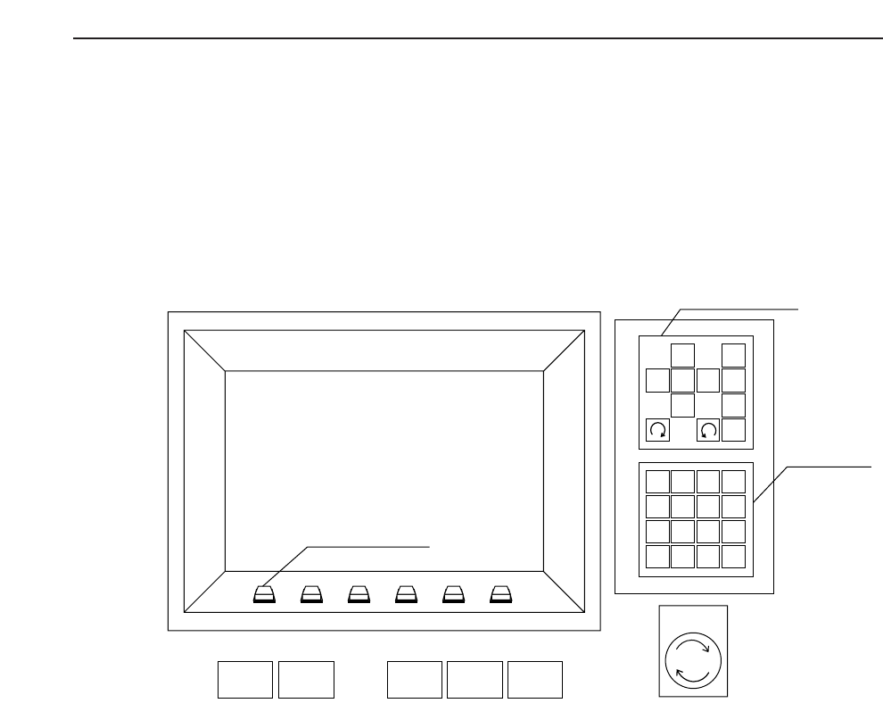
2.1. Turning On the Power Supply
Turn on the circuit breaker on the door at the bottom front of the machine.
Press the POWER ON button on the GL-541E operation panel to turn on the machine.
Note: The machine memory contents have to be cleared when the ROM chips are replaced to
upgrade the software or when the machine operates abnormally. The memory contents
are cleared by turning on the machine power supply while holding down the RESET
button. This is known as the reset-start operation.
All status data, Proper data and programs are deleted from the GL-541E memory when
the reset-start operation is carried out. Therefore, this data has to be transmitted to the
machine from F4G after the machine power supply has been turned back on. The display
following a reset-start is shown at the top of the following page.
1
2
3
4
56
7
8
9
G
#
–
F
1
2
3
4
✽
B
S
C
R
0
↑
←
↓
→
POWER
OFF
CYCLE
STOP
POWER
ON
START RESET
Inching Keys
Numerical
Keypad
Emergency
Stop
Function Keys
1 – 5
Version 2.0 GL-541E Operation

Part 1
1 – 6
Version 2.0
Chapter 2 Before Operating the Machine
2.2 Preparing for Operation
2.2.1 Operations after the Reset-Start
The Proper data, status data, and program data remain stored in the machine
memory when the machine power supply is turned off. Therefore, the following
procedure is necessary only after a reset-start or after some of the data has been
changed.
Procedure:
(1) Transmit the Proper data (data specific to the machine), status data
(machine set-up data) and programs (production data) from F4G to the
machine.
The Proper data items are described in Part 4 of this manual. Refer to the
F4G Tutorial Manual for details on how to create programs.
Note : Valid Proper data must be transferred to the machine before the
programs. If programs are transferred to a machine which contains
no valid Proper data, the program check will not operate correctly
causing errors to occur for valid programs.
(2) Press the EMERGENCY STOP button then the POWER OFF button to turn
off the machine power supply.
Note: The acceleration and deceleration coefficients for each of the
servomotor axes are only set at the time the machine power supply
is turned on. Therefore, turn the power off briefly any time any
part of the acceleration or deceleration Proper data has been
changed and transferred to the machine, not only when the reset-
start operation is carried out.
No. Prog
Page 000
v2.10
Local
Prod 00000 Sche 00000
AUTO STEP LOADER PROGRAM SET
Ready 0010B0403600 jog Z L Q
✴
Memory Back Up NG
GL-541E Operation

Chapter 2 Before Operating the Machine
Part 1
2.2.2 Zeroing the Machine
If no error occurs when the machine power supply is turned on, the operator is
prompted to zero the machine.
“Press START” and “Machine Not Zero Set” are displayed and the START
button flashes.
When the START button is pressed, the machine axes return to the zero positions
as follows:
(1) The Z1, Z2, and Z3 axes return to their respective zero positions.
(2) The X, Y, and θ axes return to their respective zero positions.
(3) When syringe 1 reaches its zero position the θ axis begins to rotate.
(4) After zeroing is completed the machine waits for a command to be input.
Note: To prevent accidents, make sure that nothing has been placed on the XY-table
before pressing the START button to zero the machine.
The GL-541E has six servomotor controlled axes: X, Y, θ, Z1, Z2, and Z3. Data
about the position of each of these axes is lost when the machine power is turned
off. Therefore, zeroing is required each time the power is turned on for the
machine to determine the position of each axis.
The method of zeroing an axis is shown below, using the X-axis as an example.
(1) If input is received from the X-axis deceleration-point switch when zeroing is
started, the axis initially moves in the +X direction until this input turns off.
Otherwise, zeroing starts from step 2.
(2) The X-axis moves in the -X direction and decelerates when an input is
received from the X-axis deceleration-point switch.
(3) After deceleration, the X-axis inches in the -X direction.
(4) The X-axis stops moving when the encoder outputs the Z signal. (The Z
signal is output only once per revolution of the motor.) The X-axis is now at
the zero position.
Speed
X-axis deceleration-point
Z signal
X+ X-
1 – 7
GL-541E OperationVersion 2.0