GL541操作手册.pdf - 第43页
Chapter 1 Operation Part 2 Proper data related to ascent of the Z-axis 190, 191, 192 : Spot_cd_timer_Z1, Z2, Z3 This timer begins counting once both the Z-axis is at the glue position and the G data application time has …

Part 2
2 – 9
Version 2.0
Chapter 1 Operation
1.3 Proper Data and Programming
Proper data related to descent of the Z-axis
181, 182, 183 : Spot_down_XY_point_Z1, Z2, Z3
Presently not used.
184, 185, 186 : Spot_down_Q_point_Z1, Z2, Z3
Presently not used.
Proper data related to operation of the glue valve
199, 200, 201 : Spot_on_XY_position_Z1, Z2, Z3
202, 203, 204 : Spot_on_Q_position_Z1, Z2, Z3
Proper data items 199, 200, 201 determine the number of pulses before the X and Y-axes
reach the glue position at which the glue valves are turned on.
Proper data items 202, 203, 204 determine the number of pulses before the q-axis reaches
the position at which the glue valves are turned on.
By inputting a larger value for these items, the G data counter starts early to reduce the
cycle time. However if the value input is too large, the glue valve will turn off in the
middle of Z-axis descent and normal glue application will not be possible.
Normally not used.
Proper data related to the descent limit of the Z-axis
196, 197, 198 : Spot_low_end_height_Z1, Z2, Z3
These items determine the height of the tip of each nozzle above the surface of the board
when the nozzle is at its lowest position. Normally they are input as negative values to
cope with warping of the boards.
190, 191, 192 : Spot_cd_timer_Z1, Z2, Z3
These timers set the time that the Z-axis remains over the board after the application time
has finished. This delay improves the glue adhesion.
GL-541E Operation

Chapter 1 Operation
Part 2
Proper data related to ascent of the Z-axis
190, 191, 192 : Spot_cd_timer_Z1, Z2, Z3
This timer begins counting once both the Z-axis is at the glue position and the G data
application time has finished. The Z-axis begins to ascend when the set time has elapsed.
Note: The maximum Z-axis speed is set with Proper data items 152, 153, 154: Max.speed_Z1,
Z2, Z3.
Proper data related to the ascent limit of the Z-axis
193, 194, 195 : Spot_up_end_timer_Z1, Z2, Z3
If the glue tends to form threads, the threads will fall along the board if the Y-table begins
to move too soon. These timers can be used to prevent this problem by setting the end
time.
The timers begin counting when the Z-axis reaches its highest limit. The Y-table cannot
begin to move to the next glue point until this set time has elapsed. For details see 1.3.2,
“Anti-Stringing Timer”.
Note: To reduce the cycle time on the GL-541E, Z_height 1, 2, 3 can be used to set the needle
(Z-axis) stroke to 4, 6, or 8 mm. For details see 1.3.1, “Z-Axis Stroke Adjustment”.
2 – 10
GL-541E Operation
Version 2.0
Part 2
2 – 11
Version 2.0
Chapter 1 Operation
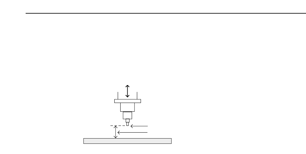
1.3.1 Z-Axis Stroke Adjustment
In order to reduce the cycle time the upper limit of the height of the needle tip
from the surface of the board (stroke height) can be changed within the program
(Machine_data Z_height 1, 2, 3) to 4, 6, or 8 mm. This setting is called the Z-axis
stroke adjustment.
When the Z_height 1, 2, or 3 in the program is reduced from the standard setting
of 8 mm to 6 mm or 4 mm, the glue dispensing cycle time is reduced by between
0.005 and 0.010 seconds.
However, when the stroke is set to 6 mm or 4 mm, stringing may occur. In order
to reduce the Z-axis stroke the following conditions must be satisfied.
• The amount of dispensed glue must be small enough to inhibit stringing.
• The needle bore must be of a diameter less than 4 mm (smaller than the
standard needle).
• The G data must be set below G10.
• Glue type used must inhibit stringing (it must be of proper viscosity, have
proper settling characteristics, etc).
Note: For details refer to the GL-541E Maintenance Manual.
• There must be no parts on the board.
Needle
Needle Stroke
Board
GL-541E Operation