GL541操作手册.pdf - 第229页
Appendix A I/O Map
Part 6
6 - 13
Version 2.0
Chapter 1 Errors Displayed by the GL-541E
1.3 Printing Data Trace for Troubleshooting
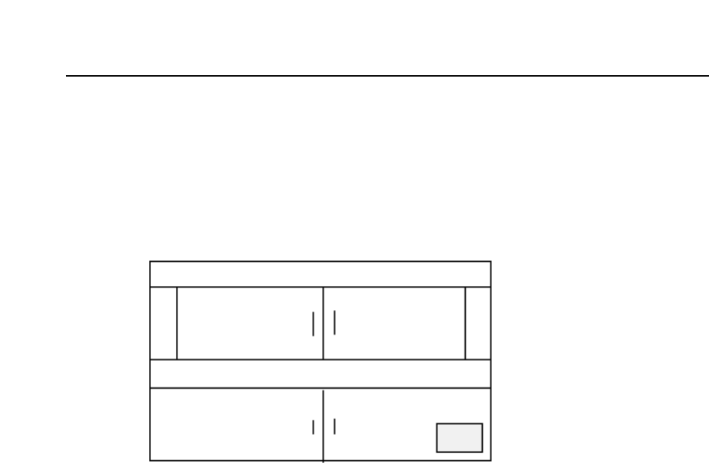
Attach the F4G printer cable to the CPU board connector. The CPU board is located on
the left side of the control box as shown in the figure below. If the machine behaves
erratically, a printout of the sequence of events which caused the problem can be
obtained.
To obtain a trace list perform the following. Switch off the machine power by pressing
the POWER OFF button and then while holding down the CYCLE STOP button press the
POWER ON button. However, if an OS error occurs, do not switch off the machine
power. Instead press the RST (reset) button on the CPU board while holding down the
CYCLE STOP button. If the power is turned off when as OS error occurs, the code will
be changed preventing the error from being accurately identified.
Note: Make the printout immediately after the failure occurs and consult Fuji.
Data about the machine operation is stored in a ring buffer. Therefore, if an operation is
carried out after the error occurs, it may delete this information from the machine. It
may not be possible to print out the trace data following the occurrence of certain types
of errors.
GL-541E Operation

Appendix A
I/O Map

Appendix A
Chapter 1 Input Port Display
A - 1Version 2.0
X000 EMERGENCY SW Emergency stop button
X001 START SW Start button
X002 RESET SW Reset button
X003 CYCLE STOP SW Cycle stop button
X004 (RESERVED)
X005 (RESERVED)
X006
X007
X008 INCHING RIGHT Inching right key
X009 INCHING LEFT Inching left key
X00A INCHING DOWN Inching down key
X00B INCHING UP Inching up key
X00C INCHING CW Inching clockwise key
X00D INCHING CCW Inching counterclockwise key
X00E
X00F SHIFT KEY Shift key
1. Input Port Display
LED No. Display Description
Input 1
GL-541E Operation