CAN Bus Workshop_Version 03__ 06_2008_DE.pdf - 第248页
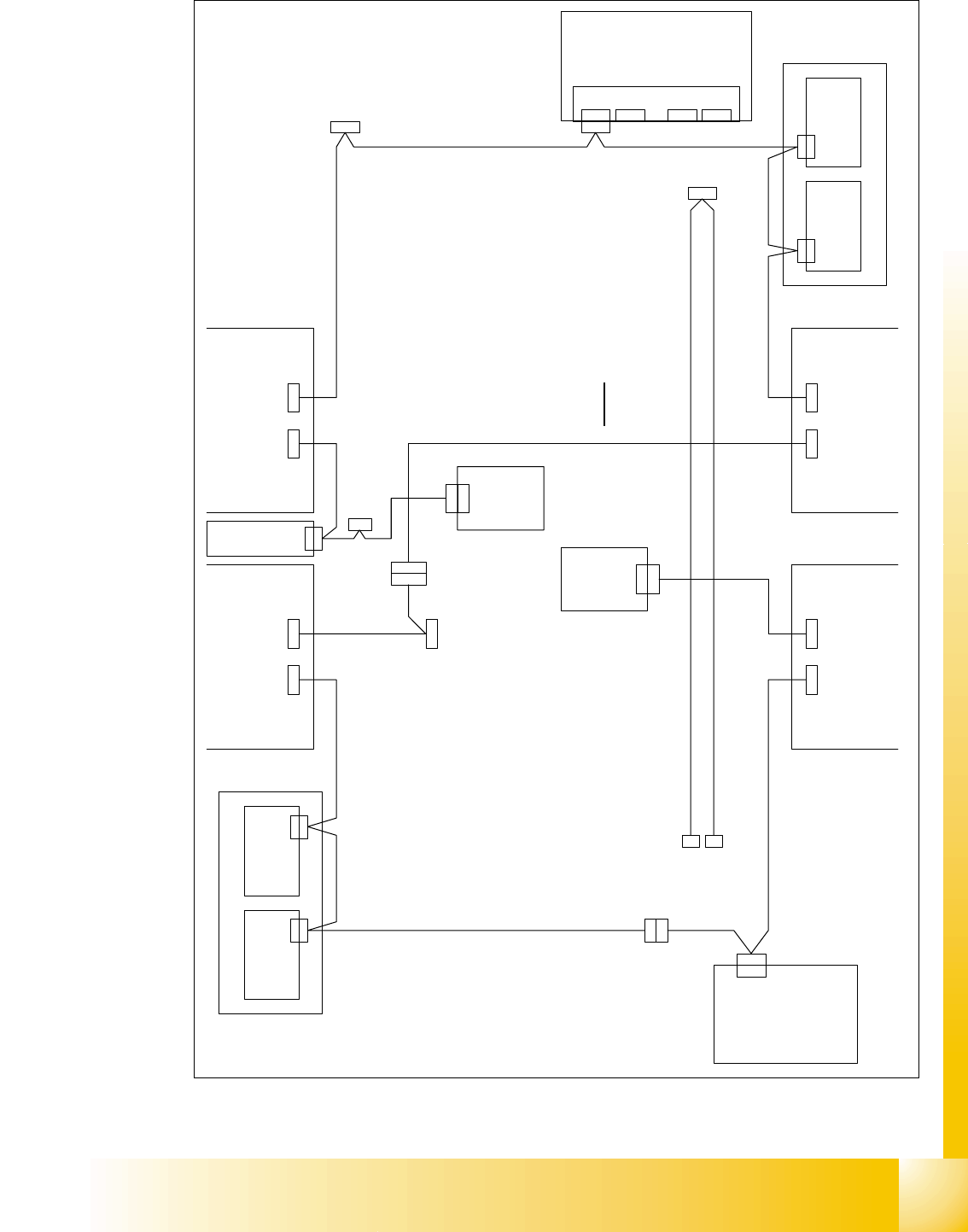
1 - 39 Siplace C AN T est Box Ausgabe 0 4/2008 1 CAN T est B ox 39 Abb. 1.10 - 18 CAN Bus S truktur ( ein CAN Bus HF mit Univ erslkabelbaum und KSP 354) V i s i o n C o n t r o l - U n i t 0 0 3 6 3 9 6 1 ( q d ) C A N M…
1 - 38
Siplace CAN Test Box
1 CAN Test Box Ausgabe 04/2008
38
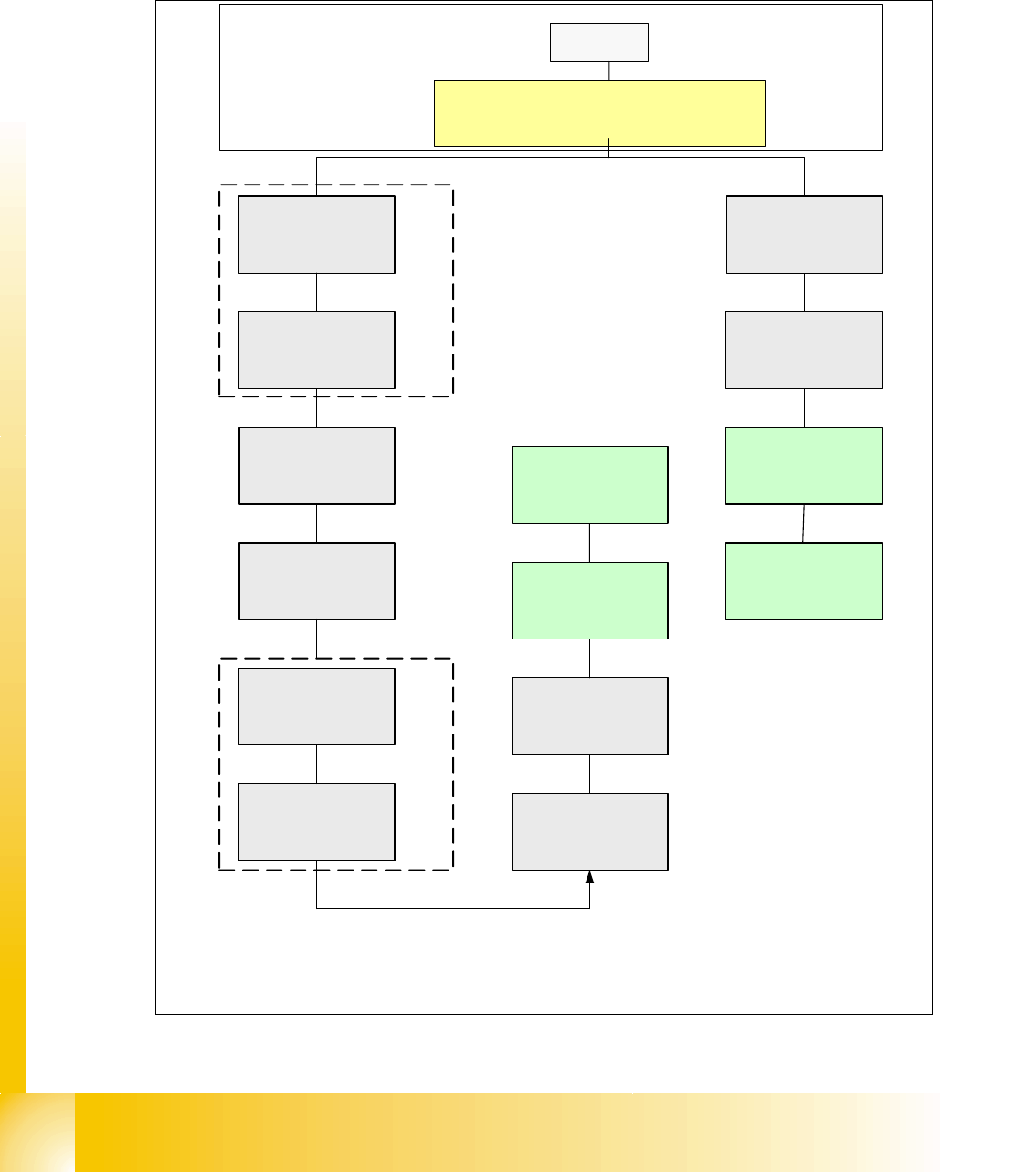
1.10.5.7 HF Can Bus Struktur mit Universalkabelbaum KSP354 (SW 504)
CAN Bus Struktur mit SW 504.xx und Com Baugruppe KSP 354 mit Universalkabelbaum (Be-
schriftung am Kabel (0301xxxx-0x), ein CAN Bus für beide Bestückbereiche.
Abb. 1.10 - 17 CAN Bus Struktur ( ein CAN Bus HF mit Universlkabelbaum KSP 354)
SMP BUS
C
O
M
U
n
i
t
K
S
P
3
5
4
MC
Axis unit
PA 2
Trailing cable-
Interface
Portal 1
CAN Bus cable
COT 3
Tape cutter
Computer Unit
One CAN Bus!
* SW Update 504 --> 505 Gantry 2 will be changed to gantry 3
new trailling cable !
old circuit diagram!
Trailing cable-
Interface
Gantry 2 *
Transport
COT 2 / MTC
Tape cutter
CAN E/
A
Modu
l
Sektor
4
CAN E/
A
Modu
l
Sektor
4
CAN E/
A
Modu
l
Sektor
4
CAN I/O
SUB Module
Section 4
Vision
Control unit
COT 1
Tape cutter
COT 4 / MTC
Tape cutter
SUB Distributor Section 4
Vision
Section 2
CAN I/O
Main Module
Section 2
Main Distributor Section 2
Section 4
Control unit
Control unit
x6pn
Head board(C500)
Gantry 1
Terminator
(120 OHM)
Head board(C500)
Gantry 2*
Terminator
(120 OHM)
1 - 39
Siplace CAN Test Box
Ausgabe 04/2008 1 CAN Test Box
39
Abb. 1.10 - 18 CAN Bus Struktur ( ein CAN Bus HF mit Universlkabelbaum und KSP 354)
V i s i o n C o n t r o l - U n i t
0 0 3 6 3 9 6 1 ( q d )
C A N
M a i n D i s t r i b u t o r
0 3 0 1 0 0 0 4 ( q a )
X 2 q d
X 2 q d
C A N
X 1 q b
X 1 q b
E i n z u g 2 E i n z u g 1
X 1 2 5X 1 2 6
C A N - I nC A N - O u t
X 1 1 5X 1 1 6
C A N - I nC A N - O u t
C A N
L P - S t e u e r u n g
X 2 2 a o
X 2 2 a o
C A N I / O - M o d u l
0 0 3 5 5 0 5 1 ( q b )
B u
S tB uS t
B uB u
0 3 0 1 0 0 5 0
B u
C A N
X 9 t q
0 3 0 1 0 0 5 1
B u
X 2 r d X 1 r b
X 1 4 5
C A N - I n
B u B u
B u
A x i s U n i t
0 3 0 1 6 1 1 0
X 9 s q
C A N
E i n z u g 3
X 1 3 6
C A N - O u t
X 4 0 c a
C A N
X 4 0 c a
0 3 0 1 0 0 5 7
S t
B u
X 2 r d
C A N
C A N I / O - M o d u l
0 0 3 5 5 0 5 1 ( r b )
X 1 r b
C A N
S u b D i s t r i b u t o r
0 3 0 1 0 0 0 5 ( r a )
V i s i o n C o n t r o l - U n i t
0 0 3 6 3 9 6 1 ( r d )
E i n z u g 4
S c h l e p p I n t e r f a c e
0 3 0 1 0 6 1 2
P 1
( c a )
S c h l e p p I n t e r f a c e
0 3 0 1 0 6 1 2
P 3
X 6 7
0 3 0 1 0 0 5 4
S t
C o m p u t e r U n i t
X 1 3 5 X 1 4 6
C A N - I n C A N - O u t
S t
B u
X 9 s q
B u
0 3 0 1 0 0 5 6
0 3 0 1 0 0 5 3
0 3 0 1 0 0 5 2
X 6 8
U m g e b u n g s d r u c k s e n s o r
P n e u m a t i k e i n h e i t
( b a )
X 6 p n
X 6 p n
B u
X 6 6
B u
X 4 0 d a
X 4 0 d a _ 2
X 4 0 d a
B u
B uS t
X 4 0 b a
X 4 0 b a
0 3 0 0 2 1 1 0
K o m m u n i k a t i o n s b a u g r u p p e
X 6 p o
X 6 6
0 3 0 1 0 0 5 5
X 6 7
B e a c h t e :
C a n - B u s - K a b e l 0 3 0 1 0 0 5 5 w i r d b e i 2 P o r t a l - M a s c h i n e n
n i c h t b e n u t z t .
A n s c h l ü s s e s i c h e r n :
V e r s e h e n t l i c h e s A
n s c h l i e ß e n s o l l n i c h t m ö g l i c h s e i n .
X 7 p nX 1 2 p n
f r e if r e if r e i
X 1 1 p n
SIPLACE HF
aktuelle CAN-Bus-Verdrahtung
1 - 40
Siplace CAN Test Box
1 CAN Test Box Ausgabe 04/2008
40
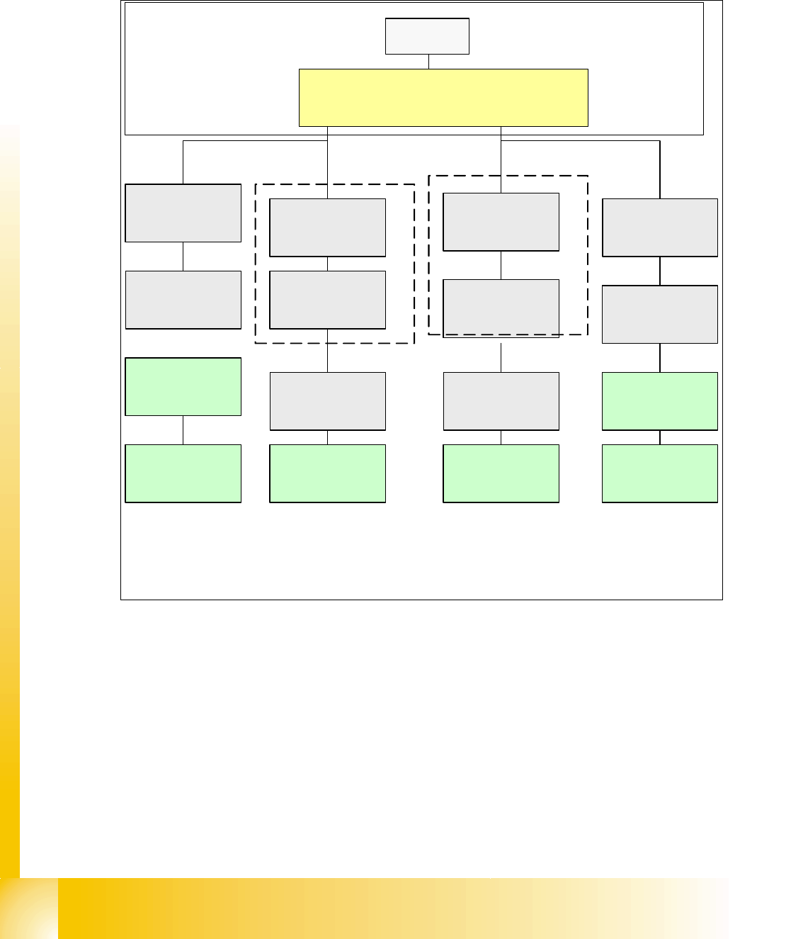
1.10.5.8 HF Can Bus Struktur mit Universalkabelbaum (SW 505-Vers.01)
CAN Bus Struktur mit SW 505.xx und Com Baugruppe KSP 354 mit Universalkabelbaum (Be-
schriftung am Kabel (0301xxxx-0x), ein CAN Bus für jeden Bestückbereich.
Abb. 1.10 - 19 CAN Bus Struktur HF (ein CAN Bus je BB, Universalkabelbaum SW 505 Version 01)
SMP BUS
C
O
M
U
n
i
t
K
S
P
3
5
4
MC
CAN Bus cable 2
Computer Unit
For each Placementarea one CAN Bus!
* with SW 505 Gantry 2 is changed to gantry 3
new cable loop!
new circuit diagram!
Trailing cable-
Interface
Gantry 1
Transport
COT 1
Tape cutter
Control unit
CAN Bus cable 1
CAN E/
A
Modu
l
Sektor
4
CAN E/
A
Modu
l
Sektor
4
CAN E/
A
Modu
l
Sektor
4
CAN I/O
SUB Module
Section 4
Vision
Control unit
SUB Distributor Section 4
Section 4
COT 4 / MTC
Tape cutter
Vision
Section 2
CAN I/O
Main Module
Section 2
Main Distributor Section 2
Control unit
COT 2 / MTC
Tape cutter
Axis unit
PA 2
COT 3
Tape cutter
Trailing cable-
Interface
Gantry 3*
x6pnx11pn
Head board(C500)
Gantry 1
Terminator
(120 OHM)
Head board(C500)
Gantry 3*
Terminator
(120 OHM)
Terminator (120 OHM)
[near the trailingcable
interface]
Terminator (120 OHM)
[near the trailingcable
interface]