CAN Bus Workshop_Version 03__ 06_2008_DE.pdf - 第82页
1 - 20 S tudent Guide CAN BUS Wor kshop 3 CAN BUS Ausga be 06/ 2008 20 35 D at um 06 /20 08 V ers io n 0 3 C A N Bu s W o rk sh o p Mat hia s M ic hel SIPL ACE Camp us Aut o matio n and Dr ives 4. CAN B us St ru ktu r S …
1 - 19
Student Guide CAN BUS Workshop
Ausgabe 06/2008 3 CAN BUS
19
33Datum06/2008 Version 03 CAN Bus Workshop Mathias Michel
SIPLACE Campus
Automation and Drives
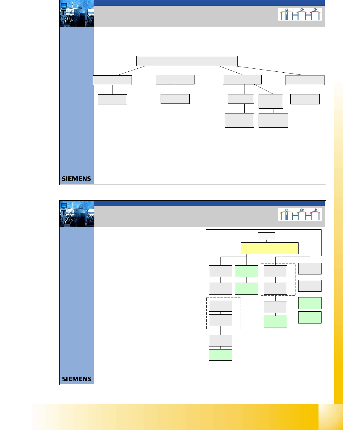
4. Überblick CAN Bus Struktur Siplace D-Serie
D- serie
D 1
D 2 D3 (X3)
Variante 1 Variante 1
D 4
Variante 1
Variante 2
Variante 3 und
WPC 4
Variante 3
mit CAN
Knoten
Va riante 2
und WPC 4
CAN BUS Siplace
34Datum06/2008 Version 03 CAN Bus W orkshop Mathias Michel
SIPLACE Campus
Automation and Drives
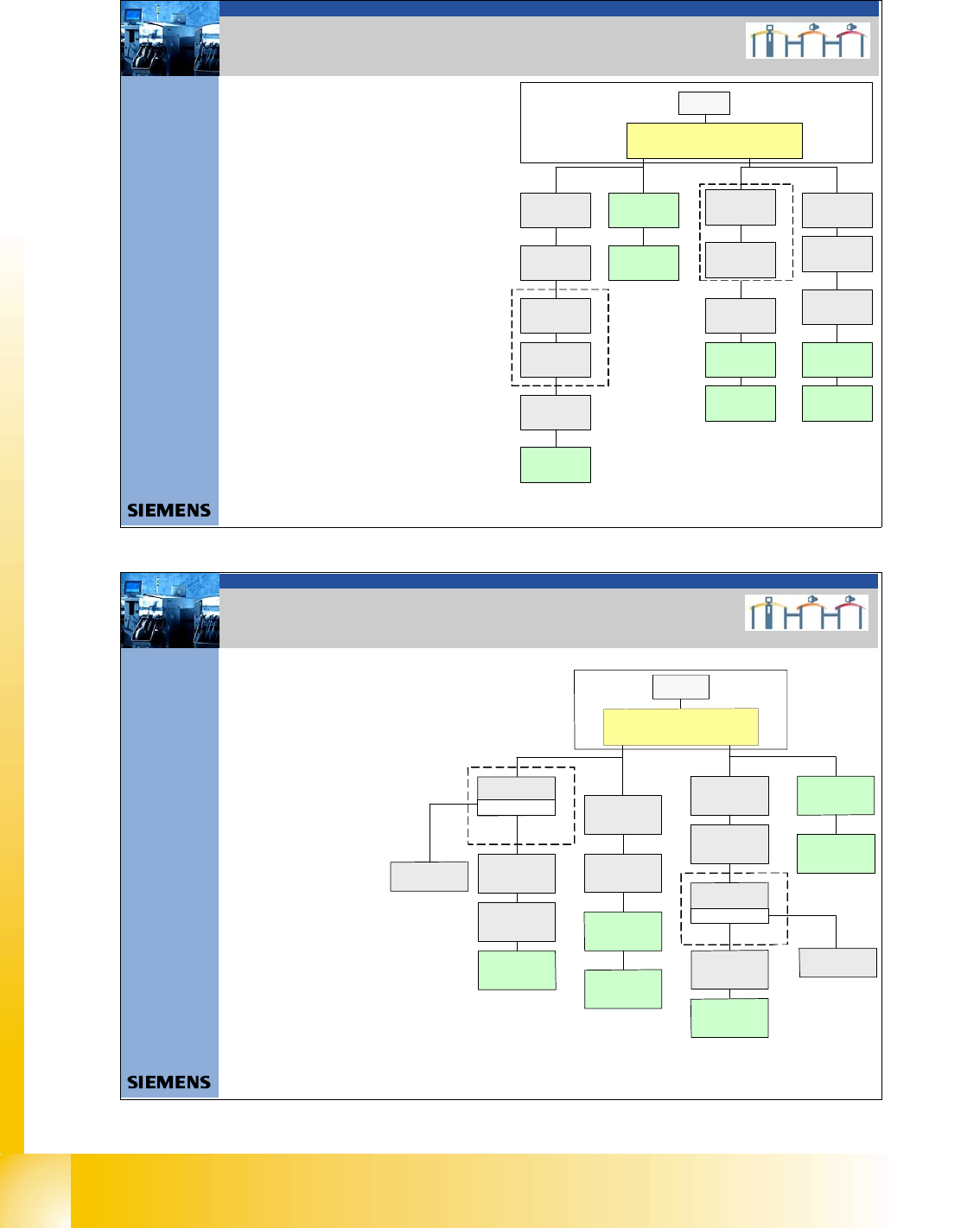
4. CAN Bus Struktur Siplace HF aktuell
SMP BUS
C
O
M
U
n
i
t
K
S
P
3
5
4
MC
CAN Bus cable 2
Computer Unit
For each Placementarea one CAN Bus!
* with SW 505 Gantry 2 is changed to gantry 3
new cable loop!
new circuit diagram!
Trailing cable-
Interface
Gantry 1
Transport
COT 1
Tape cutter
Control unit
CAN Bus cable 1
CAN E/
AModu
l
Sektor
4
CAN E/
A
Modu
l
Sektor
4
CAN E/
AModu
l
Sektor
4
CAN I/O
SUB Module
Section 4
Vision
Control unit
SUB Distributor Section 4
Section 4
COT 4 / MT C
Tape cutter
Vision
Section 2
CAN I/O
Main Module
Section 2
Main Distributor Section 2
Control unit
COT 2 / MTC
Tape cutter
Axis unit
PA 2
COT 3
Tape cutter
Trailing cable-
Interface
Gantry 3*
x6pnx11pn
Head board(C5 00)
Gantry 1
Terminator
(120 OHM)
Head board(C500)
Gantry 3*
Te rm inator
(120 OHM)
Terminator (120 OHM)
[near the trailingcab le
in ter fac e ]
Terminator (120 OHM)
[near the trailingcable
in ter fac e ]
- CAN Bus Struktur mit SW 505.xx
- Com Baugruppe KSP 354
- Universalkabelbaum
(Beschriftung am Kabel (0301xxxx-0x)
- ein CAN Bus für jeden Bestückbereich.
CAN BUS Siplace
1 - 20
Student Guide CAN BUS Workshop
3 CAN BUS Ausgabe 06/2008
20
35Datum06/2008 Version 03 CAN Bus Workshop Mathias Michel
SIPLACE Campus
Automation and Drives
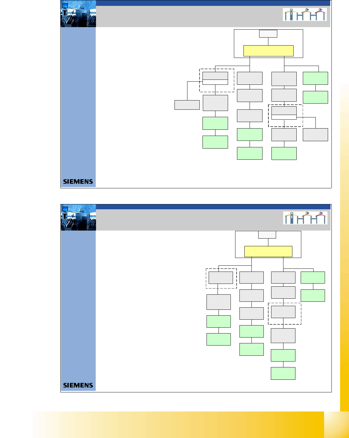
4. CAN Bus Struktur Siplace HF/3 Aktuell
- CAN Bus Struktur mit SW 505.xx
- Com Baugruppe KSP 354
- Universalkabelbaum
(Beschriftung am Kabel (0301xxxx-0x)
- ein CAN Bus für jeden Bestückbereich.
SM P BU S
C
O
M
U
n
i
t
K
S
P
3
5
4
MC
CAN Bus cable 2
Computer Unit
Trailing cable-
Interface
Gantry 4
Tr ansport
COT 1
Tape cutter
Control unit
CAN Bus cable 1
CAN E/
A
Modu
l
Se ktor
4
CAN E/
A
Modu
lSektor
4
CAN E/
A
Modu
l
Se ktor
4
CAN I/O
SUB Module
Section 4
Vision
Control unit
SUB Distributor Section 4
Section 4
COT 4
Tape cutter
Vision
Section 2
CAN I/O
Main Module
Section 2
Main Distr ibutor Section 2
Control unit
COT 2 / MTC
Tape cutter
Axis unit
PA 2
COT 3
Tape cutter
Trailing cable-
Interface
Gantry 3
x6pnx11pn
Head board(C500)
Gantry 1
Terminator
(120 OHM )
Head board(C500)
Gantry 3
Te r m ina to r
(120 OHM)
Terminator ( 120 OHM)
[near the trailingcable
interface]
Axis unit
PA 1
Head board(C500)
Gantry 4
Terminator
(120 OHM)
Trailing cable-
Interface
Gantry 1
CAN BUS Siplace
36Datum06/2008 Version 03 CAN Bus W orkshop Mathias Michel
SIPLACE Campus
Automation and Drives
4. CAN Bus Struktur Siplace X2
-CAN Bus Struktur mitSW 605.xx
- Com unit KSP 168
- Universalkabelbaum (Beschriftung am
Kabel 0301xxxx-0x)
- ein CAN Bus für jeden BB.
- Die stationären Kameras
Version >=04 haben die
Beleuchtungssteuerung
(VCU) nicht mehr in den
Sektoren 2 u. 4 sondern
direkt in den Kameras
integriert.
Der CAN Bus wird an dem
jeweiligem Stellplatz aufgetrennt
und ein zusätzlicher CAN BUS
Anschluß eingefügt.
- Bei einer X2 kann dies am
Stellplatz 1 und / oder 3 sein.
- Bei dieser Version wird das Schneidgerät,
PPW und die Sensoren der Abwurfbehälter
über den CAN Knoten gesteuert.
S
M
P
B
U
S
C
o
m
p
u
t
e
r
U
n
i
t
C
O
M
U
n
i
t
1
6
8
C
A
N
B
u
s
c
a
b
l
e
P
A
1
X
6
p
n
T
r
a
i
l
i
n
g
I
n
t
e
r
f
a
c
e
G
a
n
t
r
y
1
T
r
a
n
s
p
o
r
t
C
o
n
t
r
o
l
u
n
i
t
C
O
T
1
(
o
p
t
i
o
n
a
l
s
t
a
t
.
C
a
m
e
r
a
v
e
r
s
.
0
4
)
/
C
A
N
N
o
d
e
(
T
a
p
e
c
u
t
t
e
r
,
N
C
)
C
A
N
I
/
O
S
u
b
M
o
d
u
l
e
C
O
T
4
/
M
T
C
2
C
A
N
N
o
d
e
(
T
a
p
e
c
u
t
t
e
r
,
N
C
)
S
U
B
D
i
s
t
r
i
b
u
t
o
r
S
e
c
t
o
r
4
T
e
r
m
i
n
a
t
o
r
1
2
0
O
h
m
H
e
a
d
b
o
a
r
d
(
C
5
0
0
)
G
a
n
t
r
y
1
T
e
r
m
i
n
a
t
o
r
(
1
2
0
O
H
M
)
C
A
N
B
u
s
c
a
b
l
e
P
A
2
X
7
p
n
M
a
i
n
D
i
s
t
r
i
b
u
t
o
r
S
e
c
t
o
r
2
C
O
T
3
(
o
p
t
i
o
n
a
l
s
t
a
t
.
C
a
m
e
r
a
v
e
r
s
.
0
4
)
C
A
N
N
o
d
e
(
T
a
p
e
c
u
t
t
e
r
,
N
C
)
A
x
i
s
u
n
i
t
P
A
2
(
o
n
l
y
A
x
e
s
f
o
r
P
A
2
)
C
A
N
I
/
O
M
a
i
n
M
o
d
u
l
e
C
O
T
2
/
M
T
C
2
C
A
N
n
o
d
e
(
T
a
p
e
c
u
t
t
e
r
,
N
C
)
T
r
a
i
l
i
n
g
I
n
t
e
r
f
a
c
e
G
a
n
t
r
y
3
T
e
r
m
i
n
a
t
o
r
1
2
0
O
h
m
H
e
a
d
b
o
a
r
d
(
C
5
0
0
)
G
a
n
t
r
y
3
T
e
r
m
i
n
a
t
o
r
(
1
2
0
O
H
M
)
A
x
i
s
u
n
i
t
P
A
2
(
o
n
l
y
A
x
e
s
f
o
r
P
A
1
)
M
C
O
p
t
i
o
n
a
l
W
P
C
4
L
o
c
a
t
i
o
n
4
C
A
N
B
u
s
2
i
n
P
A
1
I
n
t
e
r
f
a
c
e
1
-
w
i
r
e
C
A
N
2
3
0
6
5
8
0
5
-
0
1
O
p
t
i
o
n
a
l
W
P
C
4
L
o
c
a
t
i
o
n
2
I
n
t
e
r
f
a
c
e
1
-
w
i
r
e
C
A
N
2
3
0
6
5
8
0
5
-
0
1
C
A
N
B
u
s
2
i
n
P
A
2
CAN BUS Siplace
1 - 21
Student Guide CAN BUS Workshop
Ausgabe 06/2008 3 CAN BUS
21
37Datum06/2008 Version 03 CAN Bus Workshop Mathias Michel
SIPLACE Campus
Automation and Drives
4. CAN Bus Struktur Siplace X3
- CAN Bus Struktur mit SW 605.xx
- Com unit KSP 168
- Universalkabelbaum
(Beschriftung am Kabel
0301xxxx-0x)
- ein CAN Bus für jeden BB
- Die stationären Kameras
Version >=04 haben die
Beleuchtungssteuerung (VCU)
nicht mehr in den
Sektoren 2 u. 4
sondern direkt in den
Kameras integriert.
Der CAN Bus wird an dem
jeweiligem Stellplatz aufgetrennt
und ein zusätzlicher CAN BUS
Anschluß eingefügt.
- Bei einer X3 kann dies am Stellplatz
1, 4 und / oder 3 sein.
- Bei dieser Version wird das Schneidgerät,
PPW und die Sensoren der Abwurfbehälter
über den CAN Knoten gesteuert.
SMP BUS
Computer Unit
C
O
M
U
n
i
t
1
6
8
CAN Bus cable
PA1
X6pn
Trailing Interface
Gantry 1
Transport
Control unit
Axis unit
PA 1
SUB Distributor Sec tor 4
Trailing Interface
Gan try 4
Hea d board (C 500)
Gantry 4
Terminator
(120 OHM)
Head board (C5 00)
Gantry 1
Terminator
(120 OH M)
CAN Bus cable
PA 2
X7pn
Main Distributor Sector 2
Axis unit
PA 2
COT 2 / MTC 2
CAN node
(Tape cutter, NC)
Te rm ina tor
120 Ohm
Trailing Interface
Gantry 3
Head bo ard (C500 )
Gantry 3
Terminator
(120 OHM)
MC
COT 4 / MTC2
CAN node
(Tape cutter, NC)
(optional stat .
Camera vers.04)
COT 3 / CAN node
(Tape cutter, NC)
(optional stat.
Ca me ra ve rs.04)
COT 1 / CAN Node
(Tape cutter, NC)
optional stat.
Came ra ve rs.04)
CAN I/O
Sub Module
Interface 1-wire CAN2
3065805 -0 1
CAN I/O
Main Module
Interface 1-wire CAN2
3065805 - 01
Optional WPC 4
Location 2
CAN Bus 2 in PA2
Optional WPC 4
Location 4
CAN Bus 2 in PA1
CAN BUS Siplace
38Datum06/2008 Version 03 CAN Bus W orkshop Mathias Michel
SIPLACE Campus
Automation and Drives
-CAN Bus Struktur mitSW 605.xx
- Com unit KSP 168
- Universalkabelbaum (Beschriftung am
Kabel 0301xxxx-0x)
- ein CAN Bus für jeden BB
- Die stationären Kameras Version >=04
haben die Beleuchtungssteuerung
(VCU) nicht mehr in den Sektoren
2 u. 4 sondern direkt in den Kameras
integriert. Der CAN Bus wird an
dem jeweiligem Stellplatz
aufgetrennt und ein zusätzlicher
CAN BUS Anschluß eingefügt.
- Bei einer X3 kann dies am Stellplatz 1,4
und / oder 2, 3 sein.
- Bei dieser Version wird das
Schneidgerät, PPW und die Sensoren
der Abwurfbehälter über den CAN
Knoten gesteuert.
4. CAN Bus Struktur Siplace X4
SMP BUS
MC
MC
Computer Unit
C
O
M
U
n
i
t
1
6
8
CAN Bus cable
PA 1
X6pn
Trailing Interface
Ga ntry 1
Transport
Control unit
COT 1 / CAN node
(Tape cutter, NC)
optional stat .
Camera vers.04)
Axis unit
PA 1
CAN I/O
Sub Module
SUB Distributor Sector 4
Trailing Interface
Ga ntry 4
Head b oard (C500 )
Gantry 4
Termi na tor
(120 OHM )
Head board( C500)
Gantry 1
Terminator
(120 OHM)
CAN Bus cable
PA 2
X7pn
Main Distributor Sector 2
Ax is u nit
PA 2
CAN I/O
Main Module
COT 2 / MTC2
CAN node
(Tape cutter, NC)
(optional stat .
Camera vers.04)
Trailing Interface
Gant ry 2
Trailing Interface
Gantry 3
Head board(C500)
Gantry 2
Terminator
(120 OHM)
Head board(C500)
Gantry 3
Terminator
(120 OHM)
COT 3 / CAN node
(Tape cutter, NC)
(optional stat.
Camera vers. 04)
COT 4 / MTC2
CAN node
(Tape cutter, NC)
(opt iona l s tat .
Camera vers.04)
CAN BUS Siplace