CAN Bus Workshop_Version 03__ 06_2008_DE.pdf - 第83页
1 - 21 S tudent Guid e CAN BU S Wor kshop Ausgabe 06/2 008 3 CAN BU S 21 37 Dat um 06 /2008 Vers io n 0 3 C AN Bu s W o r k sh op M at hias Michel SIPL ACE Cam p us Aut om atio n and Dr ives 4. CA N B u s Strukt ur Si pl…
1 - 20
Student Guide CAN BUS Workshop
3 CAN BUS Ausgabe 06/2008
20
35Datum06/2008 Version 03 CAN Bus Workshop Mathias Michel
SIPLACE Campus
Automation and Drives
4. CAN Bus Struktur Siplace HF/3 Aktuell
- CAN Bus Struktur mit SW 505.xx
- Com Baugruppe KSP 354
- Universalkabelbaum
(Beschriftung am Kabel (0301xxxx-0x)
- ein CAN Bus für jeden Bestückbereich.
SM P BU S
C
O
M
U
n
i
t
K
S
P
3
5
4
MC
CAN Bus cable 2
Computer Unit
Trailing cable-
Interface
Gantry 4
Tr ansport
COT 1
Tape cutter
Control unit
CAN Bus cable 1
CAN E/
A
Modu
l
Se ktor
4
CAN E/
A
Modu
lSektor
4
CAN E/
A
Modu
l
Se ktor
4
CAN I/O
SUB Module
Section 4
Vision
Control unit
SUB Distributor Section 4
Section 4
COT 4
Tape cutter
Vision
Section 2
CAN I/O
Main Module
Section 2
Main Distr ibutor Section 2
Control unit
COT 2 / MTC
Tape cutter
Axis unit
PA 2
COT 3
Tape cutter
Trailing cable-
Interface
Gantry 3
x6pnx11pn
Head board(C500)
Gantry 1
Terminator
(120 OHM )
Head board(C500)
Gantry 3
Te r m ina to r
(120 OHM)
Terminator ( 120 OHM)
[near the trailingcable
interface]
Axis unit
PA 1
Head board(C500)
Gantry 4
Terminator
(120 OHM)
Trailing cable-
Interface
Gantry 1
CAN BUS Siplace
36Datum06/2008 Version 03 CAN Bus W orkshop Mathias Michel
SIPLACE Campus
Automation and Drives
4. CAN Bus Struktur Siplace X2
-CAN Bus Struktur mitSW 605.xx
- Com unit KSP 168
- Universalkabelbaum (Beschriftung am
Kabel 0301xxxx-0x)
- ein CAN Bus für jeden BB.
- Die stationären Kameras
Version >=04 haben die
Beleuchtungssteuerung
(VCU) nicht mehr in den
Sektoren 2 u. 4 sondern
direkt in den Kameras
integriert.
Der CAN Bus wird an dem
jeweiligem Stellplatz aufgetrennt
und ein zusätzlicher CAN BUS
Anschluß eingefügt.
- Bei einer X2 kann dies am
Stellplatz 1 und / oder 3 sein.
- Bei dieser Version wird das Schneidgerät,
PPW und die Sensoren der Abwurfbehälter
über den CAN Knoten gesteuert.
S
M
P
B
U
S
C
o
m
p
u
t
e
r
U
n
i
t
C
O
M
U
n
i
t
1
6
8
C
A
N
B
u
s
c
a
b
l
e
P
A
1
X
6
p
n
T
r
a
i
l
i
n
g
I
n
t
e
r
f
a
c
e
G
a
n
t
r
y
1
T
r
a
n
s
p
o
r
t
C
o
n
t
r
o
l
u
n
i
t
C
O
T
1
(
o
p
t
i
o
n
a
l
s
t
a
t
.
C
a
m
e
r
a
v
e
r
s
.
0
4
)
/
C
A
N
N
o
d
e
(
T
a
p
e
c
u
t
t
e
r
,
N
C
)
C
A
N
I
/
O
S
u
b
M
o
d
u
l
e
C
O
T
4
/
M
T
C
2
C
A
N
N
o
d
e
(
T
a
p
e
c
u
t
t
e
r
,
N
C
)
S
U
B
D
i
s
t
r
i
b
u
t
o
r
S
e
c
t
o
r
4
T
e
r
m
i
n
a
t
o
r
1
2
0
O
h
m
H
e
a
d
b
o
a
r
d
(
C
5
0
0
)
G
a
n
t
r
y
1
T
e
r
m
i
n
a
t
o
r
(
1
2
0
O
H
M
)
C
A
N
B
u
s
c
a
b
l
e
P
A
2
X
7
p
n
M
a
i
n
D
i
s
t
r
i
b
u
t
o
r
S
e
c
t
o
r
2
C
O
T
3
(
o
p
t
i
o
n
a
l
s
t
a
t
.
C
a
m
e
r
a
v
e
r
s
.
0
4
)
C
A
N
N
o
d
e
(
T
a
p
e
c
u
t
t
e
r
,
N
C
)
A
x
i
s
u
n
i
t
P
A
2
(
o
n
l
y
A
x
e
s
f
o
r
P
A
2
)
C
A
N
I
/
O
M
a
i
n
M
o
d
u
l
e
C
O
T
2
/
M
T
C
2
C
A
N
n
o
d
e
(
T
a
p
e
c
u
t
t
e
r
,
N
C
)
T
r
a
i
l
i
n
g
I
n
t
e
r
f
a
c
e
G
a
n
t
r
y
3
T
e
r
m
i
n
a
t
o
r
1
2
0
O
h
m
H
e
a
d
b
o
a
r
d
(
C
5
0
0
)
G
a
n
t
r
y
3
T
e
r
m
i
n
a
t
o
r
(
1
2
0
O
H
M
)
A
x
i
s
u
n
i
t
P
A
2
(
o
n
l
y
A
x
e
s
f
o
r
P
A
1
)
M
C
O
p
t
i
o
n
a
l
W
P
C
4
L
o
c
a
t
i
o
n
4
C
A
N
B
u
s
2
i
n
P
A
1
I
n
t
e
r
f
a
c
e
1
-
w
i
r
e
C
A
N
2
3
0
6
5
8
0
5
-
0
1
O
p
t
i
o
n
a
l
W
P
C
4
L
o
c
a
t
i
o
n
2
I
n
t
e
r
f
a
c
e
1
-
w
i
r
e
C
A
N
2
3
0
6
5
8
0
5
-
0
1
C
A
N
B
u
s
2
i
n
P
A
2
CAN BUS Siplace
1 - 21
Student Guide CAN BUS Workshop
Ausgabe 06/2008 3 CAN BUS
21
37Datum06/2008 Version 03 CAN Bus Workshop Mathias Michel
SIPLACE Campus
Automation and Drives
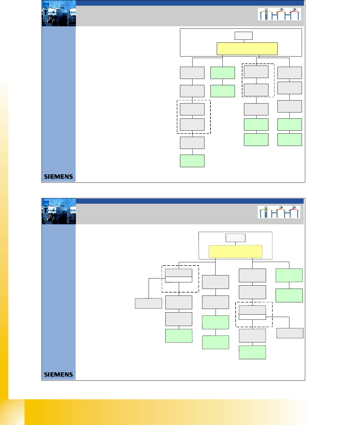
4. CAN Bus Struktur Siplace X3
- CAN Bus Struktur mit SW 605.xx
- Com unit KSP 168
- Universalkabelbaum
(Beschriftung am Kabel
0301xxxx-0x)
- ein CAN Bus für jeden BB
- Die stationären Kameras
Version >=04 haben die
Beleuchtungssteuerung (VCU)
nicht mehr in den
Sektoren 2 u. 4
sondern direkt in den
Kameras integriert.
Der CAN Bus wird an dem
jeweiligem Stellplatz aufgetrennt
und ein zusätzlicher CAN BUS
Anschluß eingefügt.
- Bei einer X3 kann dies am Stellplatz
1, 4 und / oder 3 sein.
- Bei dieser Version wird das Schneidgerät,
PPW und die Sensoren der Abwurfbehälter
über den CAN Knoten gesteuert.
SMP BUS
Computer Unit
C
O
M
U
n
i
t
1
6
8
CAN Bus cable
PA1
X6pn
Trailing Interface
Gantry 1
Transport
Control unit
Axis unit
PA 1
SUB Distributor Sec tor 4
Trailing Interface
Gan try 4
Hea d board (C 500)
Gantry 4
Terminator
(120 OHM)
Head board (C5 00)
Gantry 1
Terminator
(120 OH M)
CAN Bus cable
PA 2
X7pn
Main Distributor Sector 2
Axis unit
PA 2
COT 2 / MTC 2
CAN node
(Tape cutter, NC)
Te rm ina tor
120 Ohm
Trailing Interface
Gantry 3
Head bo ard (C500 )
Gantry 3
Terminator
(120 OHM)
MC
COT 4 / MTC2
CAN node
(Tape cutter, NC)
(optional stat .
Camera vers.04)
COT 3 / CAN node
(Tape cutter, NC)
(optional stat.
Ca me ra ve rs.04)
COT 1 / CAN Node
(Tape cutter, NC)
optional stat.
Came ra ve rs.04)
CAN I/O
Sub Module
Interface 1-wire CAN2
3065805 -0 1
CAN I/O
Main Module
Interface 1-wire CAN2
3065805 - 01
Optional WPC 4
Location 2
CAN Bus 2 in PA2
Optional WPC 4
Location 4
CAN Bus 2 in PA1
CAN BUS Siplace
38Datum06/2008 Version 03 CAN Bus W orkshop Mathias Michel
SIPLACE Campus
Automation and Drives
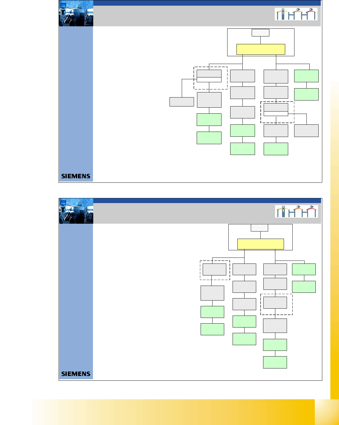
-CAN Bus Struktur mitSW 605.xx
- Com unit KSP 168
- Universalkabelbaum (Beschriftung am
Kabel 0301xxxx-0x)
- ein CAN Bus für jeden BB
- Die stationären Kameras Version >=04
haben die Beleuchtungssteuerung
(VCU) nicht mehr in den Sektoren
2 u. 4 sondern direkt in den Kameras
integriert. Der CAN Bus wird an
dem jeweiligem Stellplatz
aufgetrennt und ein zusätzlicher
CAN BUS Anschluß eingefügt.
- Bei einer X3 kann dies am Stellplatz 1,4
und / oder 2, 3 sein.
- Bei dieser Version wird das
Schneidgerät, PPW und die Sensoren
der Abwurfbehälter über den CAN
Knoten gesteuert.
4. CAN Bus Struktur Siplace X4
SMP BUS
MC
MC
Computer Unit
C
O
M
U
n
i
t
1
6
8
CAN Bus cable
PA 1
X6pn
Trailing Interface
Ga ntry 1
Transport
Control unit
COT 1 / CAN node
(Tape cutter, NC)
optional stat .
Camera vers.04)
Axis unit
PA 1
CAN I/O
Sub Module
SUB Distributor Sector 4
Trailing Interface
Ga ntry 4
Head b oard (C500 )
Gantry 4
Termi na tor
(120 OHM )
Head board( C500)
Gantry 1
Terminator
(120 OHM)
CAN Bus cable
PA 2
X7pn
Main Distributor Sector 2
Ax is u nit
PA 2
CAN I/O
Main Module
COT 2 / MTC2
CAN node
(Tape cutter, NC)
(optional stat .
Camera vers.04)
Trailing Interface
Gant ry 2
Trailing Interface
Gantry 3
Head board(C500)
Gantry 2
Terminator
(120 OHM)
Head board(C500)
Gantry 3
Terminator
(120 OHM)
COT 3 / CAN node
(Tape cutter, NC)
(optional stat.
Camera vers. 04)
COT 4 / MTC2
CAN node
(Tape cutter, NC)
(opt iona l s tat .
Camera vers.04)
CAN BUS Siplace
1 - 22
Student Guide CAN BUS Workshop
3 CAN BUS Ausgabe 06/2008
22
39Datum06/2008 Version 03 CAN Bus W orkshop Mathias Michel
SIPLACE Campus
Automation and Drives
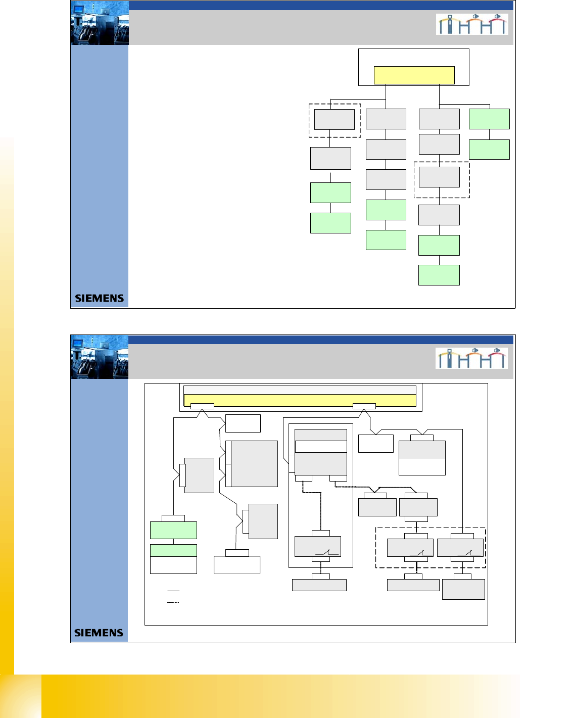
- Mit der Siplace X4I und der SW 701.xx
erfolgt die gesamte Maschinensteuerung
über einen BOX PC. D.h. Es gibt keinen
Maschinencontroller, nur die Siplace
Vision Software läuft auf dem zweiten
Box PC.
- Das Schneidgerät, PPW, die Sensoren
der Abwurfbehälter und die
Pipettenstation für die C&P20 Köpfe
werden über den CAN Knoten gesteuert.
4. CAN Bus Struktur Siplace X4I
C
O
M
U
n
i
t
1
6
8
CAN Bus cable
PA 1
X6pn
Trailing Interface
Ga ntry 1
Transport
Control unit
COT 1
CAN node
(Tape c utter, NC)
Axis unit
PA 1
CAN I/O
Sub Module
SUB Distributor Sector 4
Trailing Interface
Gantry 4
Head board(C500)
Gantry 4
Terminator
(120 OHM )
Head board(C500)
Gantry 1
Terminator
(12 0 O H M )
CAN Bus cable
PA 2
X7pn
Main Distributor Sector 2
Axis unit
PA 2
CAN I/O
Main Module
COT 2
CAN node
(Tape cutter, NC)
Trailing Interface
Ga ntry 2
Trailing Interface
Gantry 3
Head board (C500)
Gantry 2
Terminator
(120 OHM)
Head board (C 500 )
Gantry 3
Te rm in ator
(120 OHM)
COT 3
CAN node
(Tape cutter, NC)
COT 4
CAN node
(Tape cutter, NC)
Stationcomputer (Box PC)
CAN BUS Siplace
40Datum01/2007 Version 02 CAN Bus W orkshop Mathias Michel
SIPLACE Campus
Automation and Drives
4. CAN Bus Struktur Siplace D1
Micro BOX PC (Maschinen controller/ MC)
CAN Bus 1 CAN Bus 2
Transportsteuerung
TS P 2 01
CAN E/A Modul
B au ele me nte tis ch 2
(CAN Abschlußwiderstand)
Main Distributor
(Sektor 2)
CAN Interface 1 MBit/s
S1.1=ON
S1.3=ON
Gurtschneider 1
Sub Distributor
(Sektor 1 )
Ba uelem entet isc h 1
(CA N Abschl uß wider stand)
X3q e
X22ao
X4qe
X1bf
X5qe
X4ah
X4ah
X1 rb
X1af
Gurtschneider 2
X4bh
X1qa
X2qa
X12pa
X12pa2
Service-
stecker
CAN Abschluß-
widerstand
S1.5=OFF
CAN Abschluß-
widerstand S1.8=ON
X2rb
Waffe l Pa ck
Wechsler
(CAN Abschlußwiderstand)
X1rd
X30 af
X2rd
CAN BUS 2
Ax is unit
A364
X30_1sqX30_2sq
Schlep pinterfa ce
Portal 1
X40ba
CAN Bus Baudrate:
Maschinen CAN Bus 1 Mbit/s
Sub CAN Bus 1 MBit/s
X11pa
X11pa2
Service-
stecker
Portal-Kopfverteiler
Portal 1
CAN Abschluß-
wid erstand
(1MBit/s)
Stationäre
Kamera
Typ 25
X10bu
Stationäre
Kamera
Typ 36
X10au
X103
CAN Absc hluß -
widerstand
(1 Mbit/s)
CAN BUS 1
R
e
l
a
i
s
K
1
C
A
N
A
b
s
c
h
l
u
s
s
w
i
d
e
r
-
s
t
a
n
d
(
1
M
B
i
t
/
s
)
R
e
l
a
i
s
K
1
C
A
N
A
b
s
c
h
l
u
s
s
w
i
d
e
r
s
t
a
n
d
(
1
M
B
i
t
/
s
)
R
e
l
a
i
s
K
1
C
A
N
A
b
s
c
h
l
u
s
s
w
i
d
e
r
s
t
a
n
d
(
1
M
b
i
t
/
s
)
CAN BUS Siplace