00196457-05_UM_SX12DX12_SR706_EN.pdf - 第109页
User Manual SIPLACE SX1/SX2/DX1/DX2 3 Technical data and assemblies From software version SC.706.xx Version 06/2012 EN 3.4 Dimension s and weight 109 3.4.2.2 Dimensions of DX1/DX2 machine s 3 Fig. 3.4 - 2 Dimensions of D…
3 Technical data and assemblies User Manual SIPLACE SX1/SX2/DX1/DX2
3.4 Dimensions and weight From software version SC.706.xx Version 06/2012 EN
108
3.4.2 Dimensions
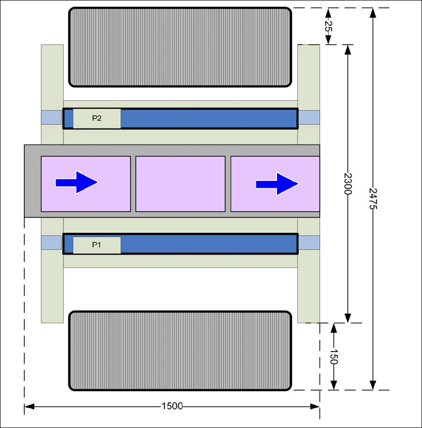
3.4.2.1 Dimensions of SX1/SX2 machines
3
Fig. 3.4 - 1 Dimensions of SX1/SX2 machine (1 component trolley inside, 1 component trolley outside
User Manual SIPLACE SX1/SX2/DX1/DX2 3 Technical data and assemblies
From software version SC.706.xx Version 06/2012 EN 3.4 Dimensions and weight
109
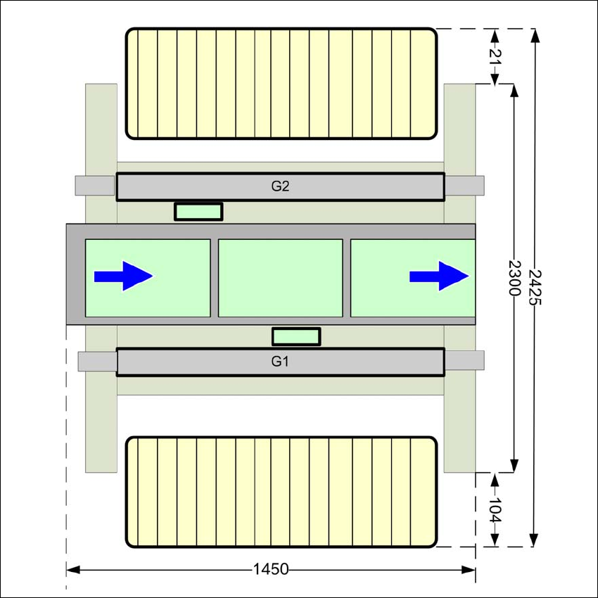
3.4.2.2 Dimensions of DX1/DX2 machines
3
Fig. 3.4 - 2 Dimensions of DX1/DX2 machine (1 DX table inside, 1 DX table outside)
3 Technical data and assemblies User Manual SIPLACE SX1/SX2/DX1/DX2
3.4 Dimensions and weight From software version SC.706.xx Version 06/2012 EN
110
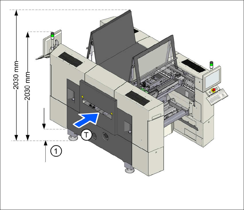
3.4.3 Height of the folded up protective cover
3
Fig. 3.4 - 3 Height of the folded-up protective cover - dimensions in millimeters (example of SX1/SX2)
The specified dimensions refer to the max. PCB conveyor height of 950 mm.
(1) The height varies according to the set PCB conveyor height
– for PCB conveyor height 900 mm = 120 mm ± 15 mm
– for PCB conveyor height 930 mm = 150 mm ± 15 mm
– for PCB conveyor height 950 mm = 170 mm ± 15 mm