00196457-05_UM_SX12DX12_SR706_EN.pdf - 第76页
2 Operational safety User Manual SIPLACE SX1/SX2/DX1/DX2 2.7 Safety equipment From software version SC.706.xx Version 06/2012 EN 76 2.7.4.2 Stru cture of the signaling circuit The following modules in the signaling circu…
User Manual SIPLACE SX1/SX2/DX1/DX2 2 Operational safety
From software version SC.706.xx Version 06/2012 EN 2.7 Safety equipment
75
2.7.4 EMERGENCY STOP loops and signaling circuit
2.7.4.1 Structure of the EMERGENCY STOP loops
The following contacts are connected in series and form the EMERGENCY STOP loop:
– Make contact elements for the two protective cover switches
– Make contact elements for the two Y axis bumper monitors (SX1/SX2 only)
– Normally open (NO) contacts for the two EMERGENCY STOP buttons
– Make contact elements for the two component trolleys/DX changeover table
– Channels for the protective contactor combination SSK K3
In the EMERGENCY STOP loop, the CAN bus signal from the signaling circuit (see section
2.7.4.2
, page 76) is fed to the protective contactor combination SSK K3. If the EMERGENCY
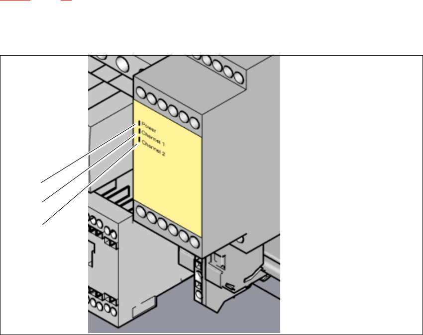
STOP loop is closed, and the signaling circuit is not signaling a malfunction, then the two green
LEDs for channels 1 and 2 light up, in addition to the green mains power check LED of the pro-
tective contactor combination.
2
Fig. 2.7 - 7 Signal LED on the protective contactor combination
(1) Mains / Power
(2) Kanal 1 / Channel 1
(3) Kanal 2 / Channel 2
(1)
(2)
(3)
2 Operational safety User Manual SIPLACE SX1/SX2/DX1/DX2
2.7 Safety equipment From software version SC.706.xx Version 06/2012 EN
76
2.7.4.2 Structure of the signaling circuit
The following modules in the signaling circuit are queried individually:
– The protective cover switches
– The Y axis bumper monitors (SX1/SX2 only)
– Signaling contact elements for the two component trolleys/DX changeover table
– EMERGENCY STOP button
All the signaling contacts are closed when the machine is on standby. If a protective cover, for ex-
ample, is raised, the associated signaling contact opens. This change of state is signaled to the
control computer via the CAN bus. An error message to this effect appears on the user interface.
2.7.4.3 Description of the functions of the EMERGENCY STOP loops
The following conditions must be fulfilled in order to start and operate the machine:
– All component trolleys/DX changeover tables must be docked in and connected.
– All protective covers must be closed.
– All Y axis stop bumpers must be fitted (SX1/SX2 only).
– Both emergency stop buttons must be released.
– The minimum operating pressure must have been reached.
– The software release ("Control ON") must be enabled, so that the start signal from the "Start"
button can switch on the SSK protective contactor combination.
– The 24 V AC/DC converter must be sending 24 V to the start buttons and the protective con-
tactor combination.
– If one of the start buttons is now pressed, the protective contactor combination SSK K3 will
switch and activate the following components:
– Intermediate circuit voltage 260 V for the gantry axes via the amplifier module A7.
– 150 VDC intermediate circuit voltage for the star axes
– The Gantry Control Unit (GCU) for the X and Y axes is addressed via the inrush current
limiter servo.
– 42 VDC operating voltage is switched to the used tape cutters.
– 42 V and 24 V are switched through for PCB conveyor control (TSP).
The machine is then ready for use.
User Manual SIPLACE SX1/SX2/DX1/DX2 2 Operational safety
From software version SC.706.xx Version 06/2012 EN 2.7 Safety equipment
77
2
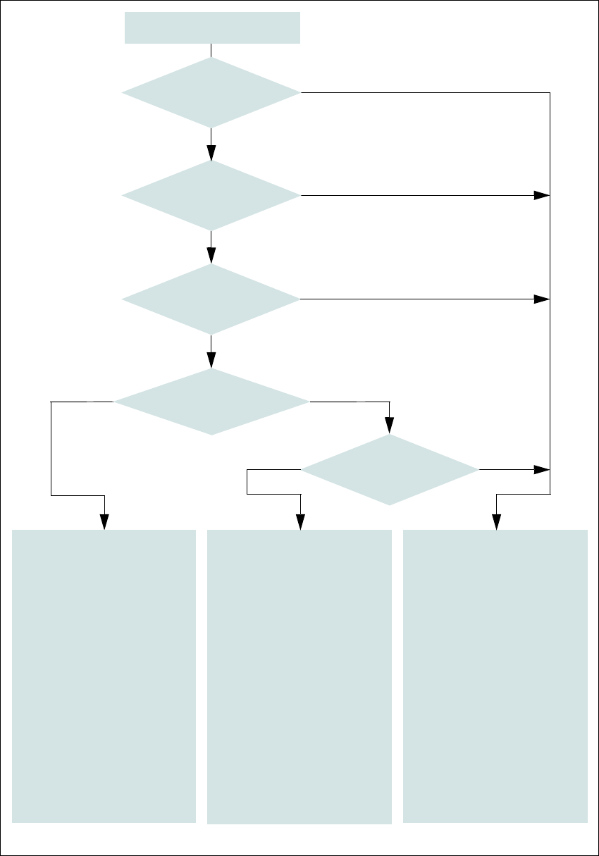
Fig. 2.7 - 8 EMERGENCY STOP loop for SIPLACE SX1/SX2
Start button pressed
No
No
Yes
No
No
Yes
Yes
No
Yes
2
Active
SSK
a
No
Voltage
Y axis 0 V-
X axis 0 V-
Star axis 0 V-
DP axis 42 V-
Z axis (C&P, TH) 42 V-
Z axis (CPP) 0 V-
Active
PCB conveyor Yes
Lifting table No
PCB clamping No
Width adjustment No
Tape cutter No
Component trolley feeding
device Yes
2
Active
SSK
a
No
Voltage
Y axis 0 V-
X axis 0 V-
Star axis 0 V-
DP axis 40 V-
Z axis (C&P, TH) 40 V-
Z axis (CPP) 0 V-
Active
PCB conveyor No
Lifting table No
PCB clamping No
Width adjustment No
Tape cutter No
Component trolley feeding
device Yes
a) SSK protective contactor combination K3
Yes
Compressed
air min. 0.5 MPa
(5.0 bar)?
EMERGENCY STOP button
pressed?
- Protective cover open?
- Is Y axis bumper missing?
Component trolley
EMERGENCY STOP circuit
interrupted?
Is safety mode enabled on
the user interface
?
2
Active
SSK
a
Yes
Voltage
Y axis 260 V-
X axis 260 V-
Star axis 150 V-
DP axis 42 V-
Z axis (C&P, TH) 42 V-
Z axis (CPP) 150 V-
Active
PCB conveyor Yes
Lifting table Yes
PCB clamping Yes
Width adjustment Yes
Tape cutter. Yes
Component trolley feeding
device Yes