00196457-05_UM_SX12DX12_SR706_EN.pdf - 第21页
User Manual SIPLACE SX1/SX2/DX1/DX2 1 Introduction From software version SC.706.xx Version 06/2012 EN 1.3 Machine description 21 1.3 Machine description 1.3.1 The SIPLACE principle The placement head s pick up the compon…

1 Introduction User Manual SIPLACE SX1/SX2/DX1/DX2
1.2 SIPLACE DX1/DX2 From software version SC.706.xx Version 06/2012 EN
20
1.2.1 Overview of placement head configuration
1
Machine Placement head Standard cameras Options
SIPLACE
DX1
C&P20 Component camera, type
23
–none
C&P12 Component camera, type
28
– Component camera, type 30
TH Component camera, type
33
– Stationary camera, type 25 (only
at location 1)
– Stationary camera, type 36
SIPLACE
DX2
C&P20 / C&P20 Component camera, type
23
–none
C&P20/C&P12
Component camera, type
23
Component camera, type
28
–none
– Component camera, type 30
C&P12/C&P12
Component camera, type
28
– Component camera, type 30
Twin Head / C&P12
Stationary camera, type 33
Component camera, type
28
– Twin Head
– Stationary camera, type 25
(only at location 1)
– Stationary camera, type 36
– C&P12
– Component camera, type 30
User Manual SIPLACE SX1/SX2/DX1/DX2 1 Introduction
From software version SC.706.xx Version 06/2012 EN 1.3 Machine description
21
1.3 Machine description
1.3.1 The SIPLACE principle
The placement heads pick up the components from the feeder modules (fixed position) on the
component trolleys, the DX table/DX changeover table or from the trays of the waffle pack changer
and then place the waiting boards.
The SIPLACE SX1/SX2 placement machine has one placement area and a single or dual con-
veyor. Two boards can be placed at the same time on dual conveyors.
The SIPLACE DX1/DX2 placement machine has one placement area and a single or dual con-
veyor. Two boards can be placed at the same time on dual conveyors.
The principle of "stationary component supply" and "stationary PCB", which have proven them-
selves in the other SIPLACE machines, offer a range of decisive benefits:
– Refilling components and splicing on tapes does not cause downtime.
– The vibration-free component feeder means that even the smallest components (e.g. 01005)
are picked up reliably.
– The PCB, which does not move during the placement process, prevents the components slip-
ping.
– The combination of placement heads with nozzle changers always guarantees an optimum
nozzle configuration for every placement process, thus minimizing traversing paths and opti-
mizing the placement sequence.
High flexibility, efficiency and reliable setups are the guarantee for top productivity in the SIPLACE
machines.
Minimum down times increase utilization and thus help to increase productivity.
1 Introduction User Manual SIPLACE SX1/SX2/DX1/DX2
1.3 Machine description From software version SC.706.xx Version 06/2012 EN
22
1.3.2 Serial number of the machine
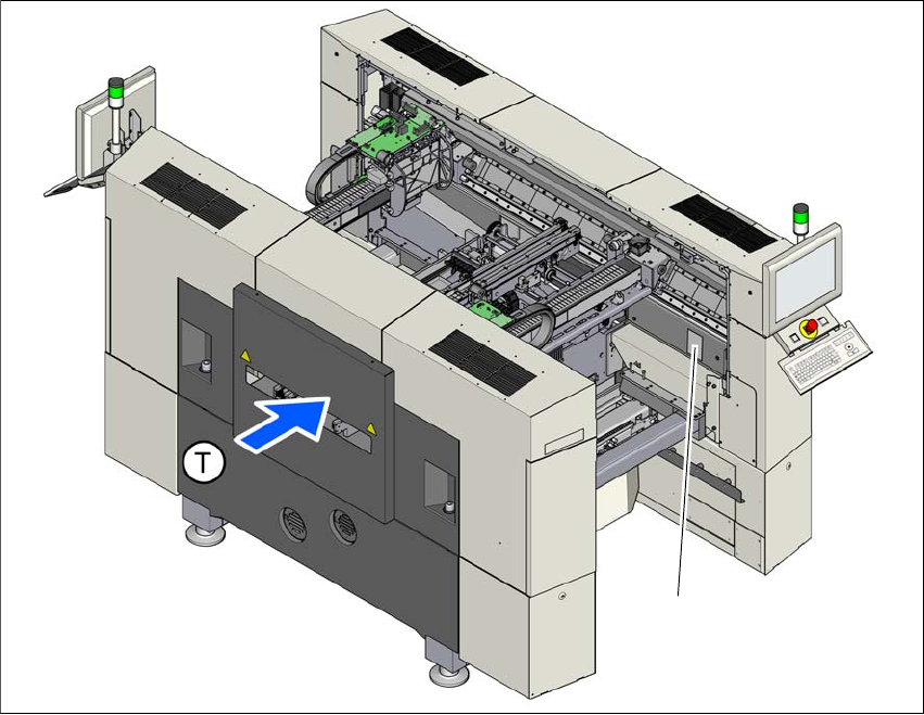
The serial number of the machine can be found on the inside of the machine frame at location 1.
1
Fig. 1.3 - 1 Position of typeplate with the serial number (example of SX1/SX2 machine)
(T) Direction of travel
(1) Typeplate
(1)