00196457-05_UM_SX12DX12_SR706_EN.pdf - 第155页
User Manual SIPLACE SX1/SX2/DX1/DX2 3 Technical data and assemblies From software version SC.706 .xx V ersion 06/2012 EN 3.9 Vision system 155 3.9.3 St ationary P&P co mponent camera, type 33, 55 x 45, digital Item n…
3 Technical data and assemblies User Manual SIPLACE SX1/SX2/DX1/DX2
3.9 Vision system From software version SC.706.xx Version 06/2012 EN
154
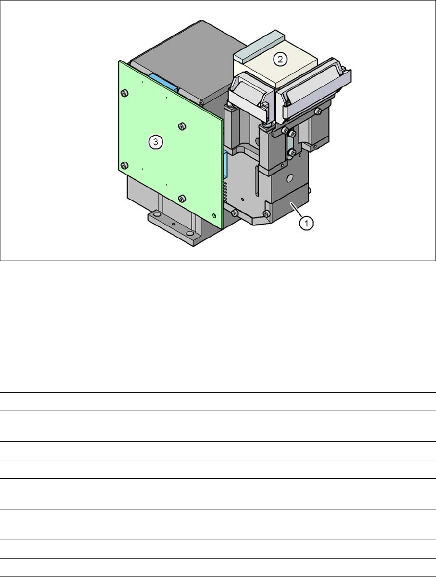
3.9.2 C&P component camera, type 30, 27 x 27, digital
3
Fig. 3.9 - 1 C&P component camera, type 30, 27 x 27, digital
(1) Component camera lens and illumination
(2) Camera amplifier
(3) Illumination control
3.9.2.1 Technical data
3
Component dimensions 0.3 mm x 0.3 mm to 27 mm x 27 mm
Component range 01005 to 27 mm x 27 mm
PLCC, SO, QFP, TSDP, SOT, MELF, CHIP, IC BGA
Min. lead pitch 0.3 mm
Min. lead width 0.15 mm
Min. ball pitch 0.25 mm for components < 18 mm x 18 mm
0.35 mm for components < 18 mm x 18 mm
Min. ball diameter 0.14 mm for components < 18 mm x 18 mm
0.2 mm for components < 18 mm x 18 mm
Field of vision 32 mm x 32 mm
Illumination type Front-illumination (5 levels, programmable as required)

User Manual SIPLACE SX1/SX2/DX1/DX2 3 Technical data and assemblies
From software version SC.706.xx Version 06/2012 EN 3.9 Vision system
155
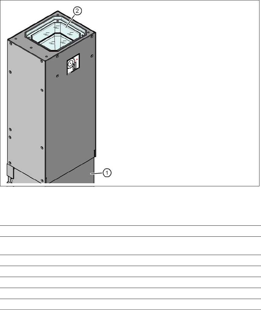
3.9.3 Stationary P&P component camera, type 33, 55 x 45, digital
Item no. 119818-xx Stationary camera, type 33
3.9.3.1 Structure
3
Fig. 3.9 - 2 Structure for the stationary P&P component camera, type 33, 55 x 45, digital
3.9.3.2 Technical data
3
(1) Camera housing with integral camera
and camera amplifier
(2) Glass plate - illumination and optics un-
derneath
Component dimensions 1.0 mm x 0.5 mm to 55 mm x 45 mm
Component range 0402, MELF, SO, PLCC, QFP, electrolytic capacitors, BGA
Min. lead pitch 0.3 mm
Min. lead width 0.15 mm
Min. ball pitch 0.35 mm
Min. ball diameter 0.2 mm
Field of vision 65 mm x 50 mm
Illumination type Front-illumination (6 levels, programmable as required)
3 Technical data and assemblies User Manual SIPLACE SX1/SX2/DX1/DX2
3.9 Vision system From software version SC.706.xx Version 06/2012 EN
156
3.9.4 Stationary component camera P&P, type 36
3.9.4.1 Structure
3
Fig. 3.9 - 3 Structure of stationary P&P component camera, type 36, 55 x 45, digital
3.9.4.2 Technical data
3
3
(1) Camera housing with integral camera
and camera amplifier
(2) Glass plate - illumination and optics un-
derneath
Component dimensions 1.6 mm x 0.8 mm to 32 mm x 32 mm
Component range 0603 to SO, PLCC, QFP, BGA, special components, bare dies,
flip-chips
Min. lead pitch 0.4 mm
Min. lead width 0.24 mm
Min. ball pitch 0.56 mm
Min. ball diameter 0.32 mm
Illumination type Front-illumination (6 levels, programmable as required)