00196457-05_UM_SX12DX12_SR706_EN.pdf - 第357页
User manual SIPLACE SX1/SX2/DX1/DX2 6 Station exte nsions From software version SC.706.xx V ersion 06/2012 EN 6.12 Magnetic pin support 357 6.12 Magnetic pin support Item no. 001 19680-xx Magnetic pi n support Wide board…
6 Station extensions User manual SIPLACE SX1/SX2/DX1/DX2
6.10 PCB alignment From software version SC.706.xx Version 06/2012 EN
356
6.10 PCB alignment
Item no. 00119677-xx PCB alignment, single conveyor
Item no. 00119678-xx PCB alignment, dual conveyor
6.10.1 Description
PCBs to be processed sometimes have a length to width ratio of 1:2 or worse. This means that
the shorter side of the PCB points in the direction of travel. During travel, such PCBs may twist
slightly and, as a result, the fiducials no longer lie within the PCB vision camera's search window.
In this case, the "PCB alignment" option ensures that these PCBs are realigned precisely at the
stopping position.
If PCBs with recesses in the direction of travel are processed, this may result in different process-
ing
positions on machines with mechanical stoppers and on machines that monitor this position with
laser light barriers. The "PCB alignment" option ensures that the PCBs are stopped at the same
position on all PCB conveyors. The "PCB alignment" option is available for both single and dual
conveyors.
The PCB is transported into the placement area until the laser light barrier triggers the stop signal
for the PCB conveyor. The lifting table with the PCB stops then moves up into a position in which
the PCB is not yet clamped and can still be moved by the conveyor belts. The two PCB stops are
level with the PCB, and the PCB supports (magnetic pins) are already in contact with the PCB.
The two conveyor belts move the PCB against the PCB stops and align them at the same time.
The lifting table then moves into its top end position, clamps the PCB and releases it from the PCB
stops so as not to affect the placement process. After the placement process, the lifting table and
PCB alignment are lowered and the PCB is moved on.
6.11 Siemens interface
Item no. 00116808-xx SIPLACE interface
The conveyor interface on the placement machines from the SX and X series is configured to the
SMEMA
standard. It is, however, still possible to use this interface in accordance with the Siemens stan-
dard. This is a significant benefit when an X-series machine is to be integrated into older SIPLACE
lines, in which case it would not be necessary to retrofit the older machines to conform to the
SMEMA standard.
Simply configure the conveyor interface of the SX series and X-series machines to the Siemens
standard and
connect the machines using the associated interface cable.
User manual SIPLACE SX1/SX2/DX1/DX2 6 Station extensions
From software version SC.706.xx Version 06/2012 EN 6.12 Magnetic pin support
357
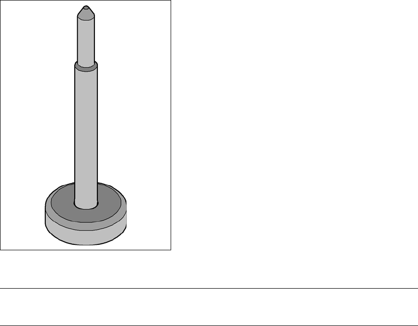
6.12 Magnetic pin support
Item no. 00119680-xx Magnetic pin support
Wide boards tend to deflect during placement such that, under certain circumstances, the compo-
nents can no longer be placed with the desired accuracy. Highly curved PCBs also affect the
placement accuracy. This problem can be easily rectified by fitting magnetic pin supports on the
lifting table.
6
Fig. 6.12 - 1 Magnetic pin support
NOTE
The free positioning of magnetic pin supports is limited by the stop bar of the board conveyor. 6
6 Station extensions User manual SIPLACE SX1/SX2/DX1/DX2
6.13 Vacuum pump From software version SC.706.xx Version 06/2012 EN
358
6.13 Vacuum pump
6.13.1 Safety instructions for vacuum pumps
WARNING 6
Please observe the safety instructions in the operating manual supplied!
6.13.2 Description
Each Collect&Place head has its own vacuum generator, which supplies the holding and place-
ment circuit with the required vacuum. The vacuum generator for the placement heads functions
according to the Venturi principle. When operated together with a vacuum pump, the SpeedStar
(C&P20) can reduce the compressed air consumption considerably. The running costs will fall ac-
cording to the energy costs incurred.
PLEASE NOTE 6
The compressed air consumption values with the vacuum pump can be found in section 3.3.4
,
page 106.
6.14 Long board option (LBO)
The "Long board" option allows you to place boards which exceed the specified board length. The
maximum length is 610 mm.