00196457-05_UM_SX12DX12_SR706_EN.pdf - 第136页
3 Technical data and assemblies Us er Manual SIPLACE SX1/SX2/DX1/DX2 3.6 Placement head From software version SC.706.xx Version 06/2012 EN 136 3.6.4 12 segment Collect&Pl ace head (DX1/DX2 only) 3 Fig. 3.6 - 10 12 se…
User Manual SIPLACE SX1/SX2/DX1/DX2 3 Technical data and assemblies
From software version SC.706.xx Version 06/2012 EN 3.6 Placement head
135
3.6.3.2 Technical data
Optical centering with SIPLACE TwinStar
Fine-pitch camera
(component camera type
33)
SIPLACE TwinStar
Fine-pitch camera
(component camera type
36
a
)
SIPLACE TwinStar
Flip-Chip camera
(component camera type
25)
Component range
b
0402 to SO, PLCC, QFP,
BGA, special components,
bare dies, flip-chips
0603 to SO, PLCC, QFP,
BGA, special components,
bare dies, flip-chips
0201 to SO, PLCC, QFP,
sockets, plugs, BGA, spe-
cial components, bare dies,
flip-chips, shields
Component specs
c
max. height 25 mm 25 mm 25 mm
min. lead pitch 0.3 mm 0.4 mm 0.25 mm
min. lead width 0.15 mm 0.24 mm 0.1 mm
min. ball pitch 0.35 mm 0.56 mm 0.14 mm
min. ball diameter 0.2 mm 0.32 mm 0.08 mm
min. dimensions 1.0 mm x 0.5 mm 1.6 mm x 0.8 mm 0.6 mm x 0.3 mm
max. dimensions
Single measurement 55 mm x 45 mm 32 mm x 32 mm 16 mm x 16 mm
Multiple measurement -- -- 55 mm x 55 mm
For use with two nozzles: 50 mm x 50 mm or 69 mm x 10 mm --
For use with one nozzle: 78 mm x 78 mm or 110 mm x 10 mm
up to 200 mm x 110 mm (with restrictions)
--
max. weight
d
100 g 100 g 100 g
Programmable set-down
force
1.0 N - 15 N
2.0 N - 30 N
e
1.0 N - 15 N
2.0 N - 30 N
d
1.0 N - 15 N
2.0 N - 30 N
d
Nozzle types
f
5xx (standard)
4xx + adapter
8xx + adapter
9xx + adapter
gripper
5xx (standard)
4xx + adapter
8xx + adapter
9xx + adapter
gripper
5xx (standard)
4xx + adapter
8xx + adapter
9xx + adapter
gripper
Nozzle spacing for P&P heads 70.8 mm 70.8 mm 70.8 mm
X/Y accuracy
g
± 26 µm/3± 35 µm/4 ± 36 µm/3± 50 µm/4 ± 22 µm/3± 30 µm/4
Angular accuracy ± 0.05° / 3± 0.07°/ 4 ± 0.05° / 3± 0.07°/ 4 ± 0.05° / 3± 0.07° / 4
Illumination level 6 6 6
Possible illumination level
settings
256
6
256
6
256
6
a) For SIPLACE DX1/DX2 only
b) Please note that the placeable component range is also affected by the pad geometry, the customer-specific standards, the
component packaging tolerances and the component tolerances.
c) If the MultiStar and TwinStar are combined in the same placement area, the maximum component height may be restricted.
d) If standard nozzles are used
e) SIPLACE High-Force Head.
f) Over 300 different nozzles and 100 gripper types are available, with an extensive nozzle database available online.
g) The accuracy value, measured using the vendor-neutral IPC standard.
3 Technical data and assemblies User Manual SIPLACE SX1/SX2/DX1/DX2
3.6 Placement head From software version SC.706.xx Version 06/2012 EN
136
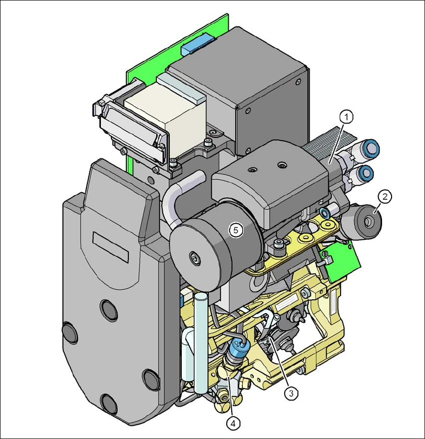
3.6.4 12 segment Collect&Place head (DX1/DX2 only)
3
Fig. 3.6 - 10 12 segment Collect&Place head - function groups part 1
3
(1) Vacuum generator
(2) Turning station, DP axis
(3) Star with 12 sleeves, star axis
(4) Blast air valve
(5) Silencer
User Manual SIPLACE SX1/SX2/DX1/DX2 3 Technical data and assemblies
From software version SC.706.xx Version 06/2012 EN 3.6 Placement head
137
3
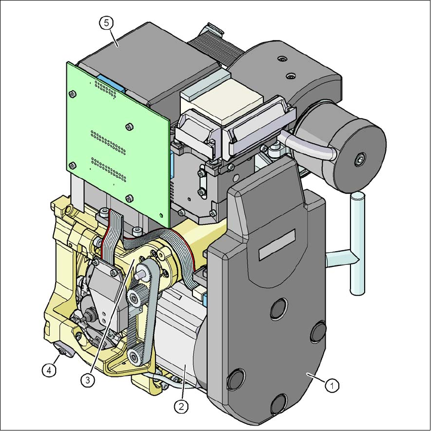
Fig. 3.6 - 11 12 segment Collect&Place head - function groups part 2
3
(1) Intermediate distributor board (under the cover)
(2) Star drive - DR motor
(3) Z axis motor
(4) Valve adjustment drive
(5) C&P component camera, type 28 (18 x 18) digital (standard camera)
or type 30 (18 x 18) digital, high-resolution