00196457-05_UM_SX12DX12_SR706_EN.pdf - 第236页
4 Setting up and commissioning User Manual SIPLACE SX1/SX2/DX1/DX2 4.4 Adjusting the component trolley to the PCB conveyor height From software version SC.706.xx Version 06/2012 EN 236 4.4 Adjusting the component trolley…

User Manual SIPLACE SX1/SX2/DX1/DX2 4 Setting up and commissioning
From software version SC.706.xx Version 06/2012 EN 4.3 Setting up the machine
235
4.3.10 Removing the shipping braces
The shipping braces are attached to the linear guides. Each gantry is fastened with two shipping
braces on the X and Y axes.
Remove all the shipping braces from the gantry axes.
If the SIPLACE machine needs to be transported, always fit the shipping braces back onto
the conveyor.
4.3.11 Removing the corrosion protection from the guide rails
The machines were given a corrosion protection treatment before they were delivered.
CAUTION 4
– You should therefore remove the corrosion protection from all the axes and bearings when
you traverse the machine axes for the first time during commissioning.
– Grease all the axes and bearings with the grease described in the maintenance instructions.
If the corrosion protection agent is mixed with the bearing grease on the axes this can greatly re-
duce the service life of the bearings and guide rails.
CAUTION 4
Do not allow any alcohol to enter the guide carriages when you clean the guide rails and scale
rods. Alcohol will damage the bearing grease in the guide carriages.
4 Setting up and commissioning User Manual SIPLACE SX1/SX2/DX1/DX2
4.4 Adjusting the component trolley to the PCB conveyor height From software version SC.706.xx Version 06/2012 EN
236
4.4 Adjusting the component trolley to the PCB conveyor
height
The component trolley can be easily and quickly adjusted to the following PCB conveyor heights:
900 mm 4
930 mm (standard height) 4
950 mm (SMEMA height) 4
4
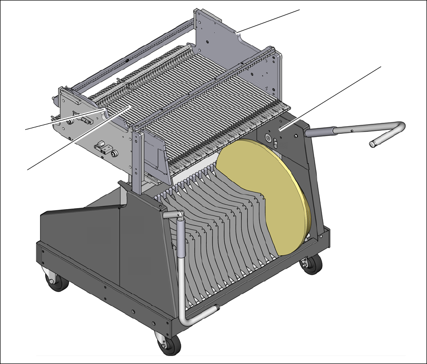
Fig. 4.4 - 1 Component trolley 60
(1) Holes for the transport heights of 900, 930 and 950 mm.
(2) changeover table
(3) M8 holes for fixing the mounting device
(1)
(2)
(3)
(3)

User Manual SIPLACE SX1/SX2/DX1/DX2 4 Setting up and commissioning
From software version SC.706.xx Version 06/2012 EN 4.4 Adjusting the component trolley to the PCB conveyor height
237
4.4.1 Warning instructions
WARNING 4
Only ASM engineers or qualified personnel are permitted to adjust the component trolley height.
Always follow the applicable accident prevention regulations.
Remove all the feeder modules from the changeover table, if you want to adjust the height for
the changeover table.
4.4.2 Tools and equipment
You will need the following tools and equipment to adjust the height of the component trolley:
– Mounting device (item no. 03015976-xx)
– Lifting device for raising the component trolley table, carrying capacity at least 80 kg
4.4.3 Changing the component trolley height
WARNING 4
Remove all the feeder modules from the changeover table.
Fit the mounting device to the changeover table in order to adjust the height. This prevents
the changeover table becoming deformed when the table is raised or lowered.
Fix the fit-up aid to the changeover table with the two M8 x 50 hexagon socket head screws.
There are two different holes available for the changeover table 60 and the changeover table
30.
Hook the leverage device into the eyelet.
Loosen the fastening screws and lift the changeover table into the required position.
Fit and tighten the fastening screws.