00196457-05_UM_SX12DX12_SR706_EN.pdf - 第69页
User Manual SIPLACE SX1/SX2/DX1/DX2 2 Operational safety From software version SC.706.xx Version 06/2012 EN 2.7 Safety equipment 69 2 Fig. 2.7 - 4 Position of switches and buttons - View of the PCB input side (example of…
2 Operational safety User Manual SIPLACE SX1/SX2/DX1/DX2
2.7 Safety equipment From software version SC.706.xx Version 06/2012 EN
68
2.7.2 Switches and buttons on the machine
2.7.2.1 Position of switches and buttons on the machine
2
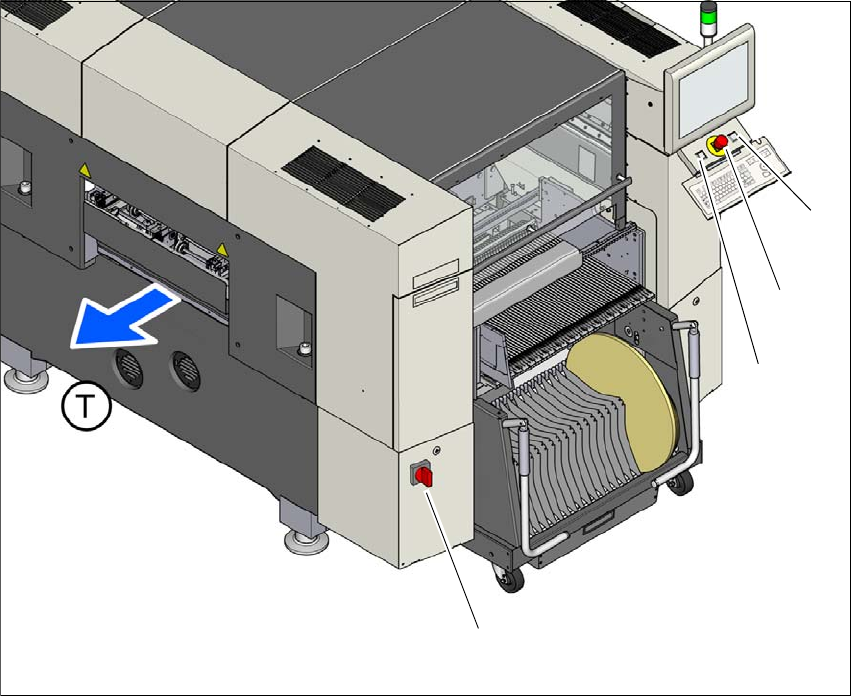
Fig. 2.7 - 3 Position of switches and buttons - View of the PCB output side (example of SX1/SX2)
(1) Main power switch
(2) Start button (green)
(3) EMERGENCY STOP button
(4) Stop button (black)
(T) PCB transport direction
(2)
(1)
(3)
(4)
User Manual SIPLACE SX1/SX2/DX1/DX2 2 Operational safety
From software version SC.706.xx Version 06/2012 EN 2.7 Safety equipment
69
2
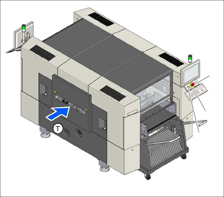
Fig. 2.7 - 4 Position of switches and buttons - View of the PCB input side (example of SX1/SX2)
(1) Start button (green)
(2) EMERGENCY STOP button
(3) Stop button (black)
(T) PCB transport direction
(3)
(1)
(2)
2 Operational safety User Manual SIPLACE SX1/SX2/DX1/DX2
2.7 Safety equipment From software version SC.706.xx Version 06/2012 EN
70
2.7.2.2 Position of protective switches on the machine
2
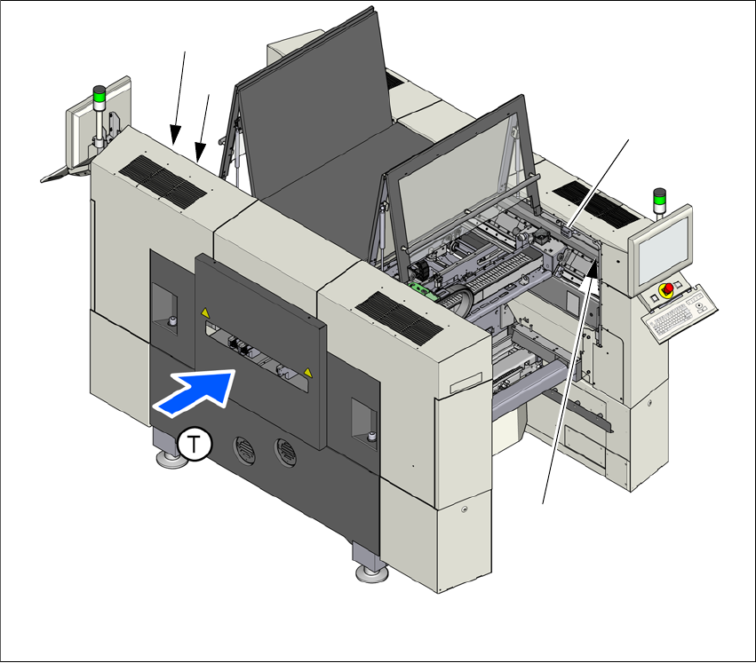
Fig. 2.7 - 5 Position of the protective cover switches on the machine (example of SX1/SX2)
(1) Protective cover switch, location 1
(2) Protective cover switch, location 2
(3) Protective cover switch for bumper detection (SX1/SX2 only)
(T) PCB transport direction
(2)
(1)
(3)
(3)