00196457-05_UM_SX12DX12_SR706_EN.pdf - 第290页
5 Working with the machine User Manual SIPLACE SX1/SX2/DX1/DX2 5.11 Observing displays on the X feeder module From software version SC.706.xx Version 06/2012 EN 290 5.1 1.3 S t atus display –G r e e n : The feeder module…
User Manual SIPLACE SX1/SX2/DX1/DX2 5 Working with the machine
From software version SC.706.xx Version 06/2012 EN 5.11 Observing displays on the X feeder module
289
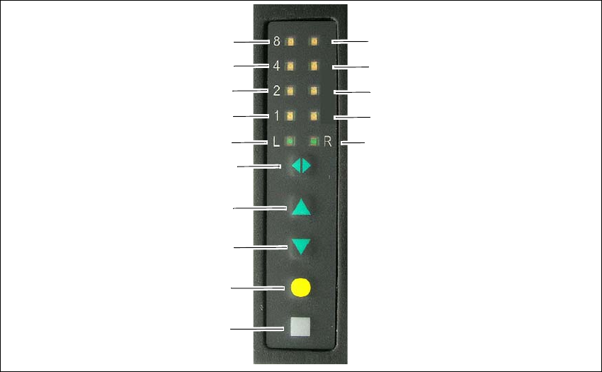
5.11.2 Feeder module with LED display
The X feeder modules (2x8 mm, smart feeder 12 mm and smart feeder 16 mm) have a multicol-
ored status display for each track and LED display, to indicate the operating states.
5
Fig. 5.11 - 2 Buttons, LED and status displays on the 2x8 mm X feeder module
(1) SET button
(2) FOIL button
(3) BACK button
(4) FORWARD button
(5) Track change button for switching between right and left
(6) LED L left track active
(7) LED 1 mm increment for left track
(8) LED 2 mm increment for left track
(9) LED 4 mm increment for left track
(10) LED 8 mm increment for left track
(11) LED R right track active
(12) LED 1 mm increment for right track
(13) LED 2 mm increment for right track
(14) LED 4 mm increment for right track
(15) LED 8 mm increment for right track
(1)
(2)
(3)
(4)
(5)
(6)
(7)
(8)
(9)
(10)
(15)
(14)
(13)
(12)
(11)

5 Working with the machine User Manual SIPLACE SX1/SX2/DX1/DX2
5.11 Observing displays on the X feeder module From software version SC.706.xx Version 06/2012 EN
290
5.11.3 Status display
–Green:
The feeder module is on standby and is contained in the current setup.
– Orange:
A warning is being signalized. The text of the warning appears on the LCD display.
– Red:
A malfunction has occurred. The error message is output on the LCD display.
–Off:
The feeder module is not in the current setup.
PLEASE NOTE 5
The machine controller switches off the status display of any feeder modules not included in the
setup. The "LED off" status only occurs when the programming system has preset a job on the
line. This takes some of the work away from the operator since he only has to watch those feeder
modules that are contained in the setup.
For the actual setup process - no setup information at the station, no job sent from SIPLACE Pro
to the station/line - the LED on each feeder module is activated after the setup has been made.
The operator is thus informed whether everything is OK.
5.11.4 LCD display
The following tables containing the wording of the LCD display, the color and the mode of the sta-
tus display, its meaning and troubleshooting measures.
5.11.4.1 Warnings and remedies
5
5
Text on the
LCD display
Status
display
Meaning Troubleshooting
Remove Foil
(Remove the foil)
Orange The selected function is not
permitted when the cover foil
is tensioned (foil rocker is
pressed down).
If you wish to carry out that function, remove
the foil from the pair of gear wheels and cut
it off to relieve the pressure on the foil rocker.

User Manual SIPLACE SX1/SX2/DX1/DX2 5 Working with the machine
From software version SC.706.xx Version 06/2012 EN 5.11 Observing displays on the X feeder module
291
5.11.4.2 Error messages and remedies
5
Text on the
LCD display
Status
display
Meaning Troubleshooting
none Red,
flashing
Feeder module software not
jumping to the application
Reload the application software
Load feeder module software
Handle --->>
(Handle --->>)
Red Feeder module was sig-
naled, but removal handle is
not yet pushed in
Push in the removal handle
Low Voltage
(Low voltage)
Orange 24V supply voltage did not
rise above the switch-on
threshold after switching on
Check the power supply
Low Voltage
(Low voltage)
Red 24V supply voltage rose
above the switch-on thresh-
old after switching on and
was then interrupted
Check the power supply
Feed Timeout
TransTimeout
(Timeout in tape
feeder cycle)
Red Tape feeder cycle did not
end correctly within the spec-
ified time (timeout for the
"Feed" function)
Is the tape reel jammed in the container?
Is there a component jammed in the pick-up
area between component tape and compo-
nent window?
Once the obstacle has been eliminated, use
the arrow keys to restart the conveyor. The
feeder module will move the defective con-
veyor to the end, and then returned to its
position
Foil Torn
(Foil torn)
Red Foil was not tensioned within
the specified time
The foil is probably torn. Insert new foil and
tension
Foil PeelErr
(Error while peel-
ing off the foil)
Red Foil was not peeled off even
though the tape is moved
The cover foil is probably jammed beneath
the pick-up window and cannot be peeled
off correctly
Foil Jam
(Foil jam)
Red Foil motor has locked up Leveling gears blocked by foil? => Remove
the foil
EEP-WriteErr
(Error while back-
ing up data in the
EEPROM)
Red The data back-up in the EE-
PROM was not carried out
correctly
Remove the component tape (tape can be
moved out by pressing the arrow keys or
pulled out after raising the pick-up window).
Press the SET button to confirm the error.
Then press the yellow button to confirm the
reference run prompt.
EEP-ReadErr
(Error while read-
ing
the EEPROM)
Red Data was not read from the
EEPROM correctly
EEP-DataErr
(Error while back-
ing up the data in
the EEPROM)
Red The data back-up in the EE-
PROM was not carried out
fully