00196457-05_UM_SX12DX12_SR706_EN.pdf - 第80页
2 Operational safety User Manual SIPLACE SX1/SX2/DX1/DX2 2.8 Residual voltages and discharge times in the mach ine From software version SC.706.xx Version 06/2012 EN 80 2.8 Residual volt ages and discharge times in the m…
User Manual SIPLACE SX1/SX2/DX1/DX2 2 Operational safety
From software version SC.706.xx Version 06/2012 EN 2.7 Safety equipment
79
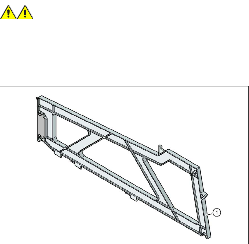
2.7.5 Hand guard
2.7.5.1 Hand guard at the locations
WARNING 2
The operational safety of the component trolley in the SIPLACE SX1/SX2 and of the DX table or
DX changeover table in the SIPLACE DX1/DX2 is ensured if at least every second free location
is occupied with a feeder module or hand guard (dummy feeder). When a waffle pack holder is
set up, every other free locations should again be protected again with a hand guard. In other
words, there must be no more than one free location between two adjacent feeder modules or
feeder module and waffle pack tray holder.
Fig. 2.7 - 10 Hand guard on the component trolley locations, on the DX table or DX changeover table
2
(1) Dummy feeder SIPLACE X, item no. 00141226-xx
2 Operational safety User Manual SIPLACE SX1/SX2/DX1/DX2
2.8 Residual voltages and discharge times in the machine From software version SC.706.xx Version 06/2012 EN
80
2.8 Residual voltages and discharge times in the machine
If the EMERGENCY STOP button is pressed or the machine is switched off, the 260 VDC link volt-
age for the gantry axes and the 150 VDC link voltage for the star axes are reduced to harmless
residual voltages in a very short time.
WARNING 2
The machine is supplied with 3 x 200 V~, 3 x 208 V~, 3 x 220 V~, 3 x 230 V~, 3 x 380 V~,
3x400V~ or 3x415V~ ± 5%, 50/60Hz mains voltage. This means that some parts of the sys-
tem carry potentially lethal voltages - even when switched off at the main power switch. Incorrect
handling of the machine can therefore result in death or severe injury or considerable damage to
equipment.
Always follow the applicable accident prevention and DIN regulations (particularly EN 60204,
part 1 or IEC 60204, part 1) and the applicable regulations in your own country.
The covers over the power supply unit may ONLY be opened by appropriately qualified and
trained personnel.
2
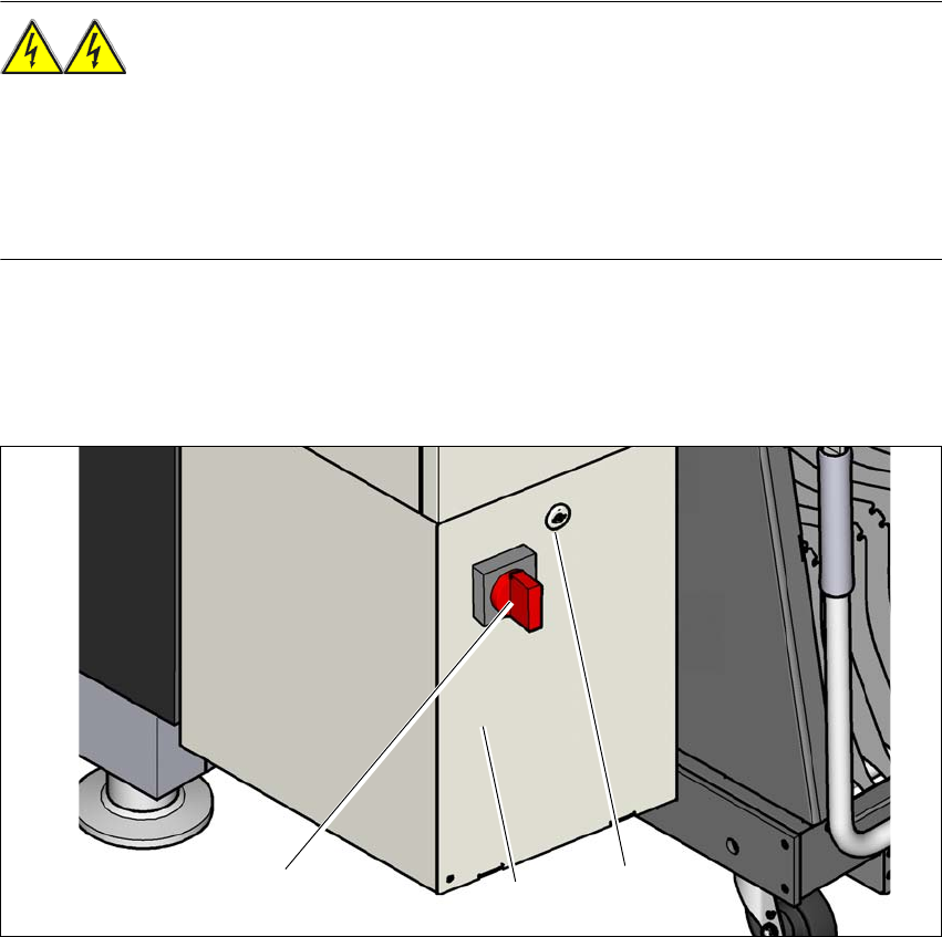
Fig. 2.8 - 1 Power supply unit (example of SX1/SX2)
(1) Main power switch
(2) Power supply unit behind the cover
(3) Padlock with bolt in the cover
(3)
(1)
(2)
User Manual SIPLACE SX1/SX2/DX1/DX2 2 Operational safety
From software version SC.706.xx Version 06/2012 EN 2.8 Residual voltages and discharge times in the machine
81
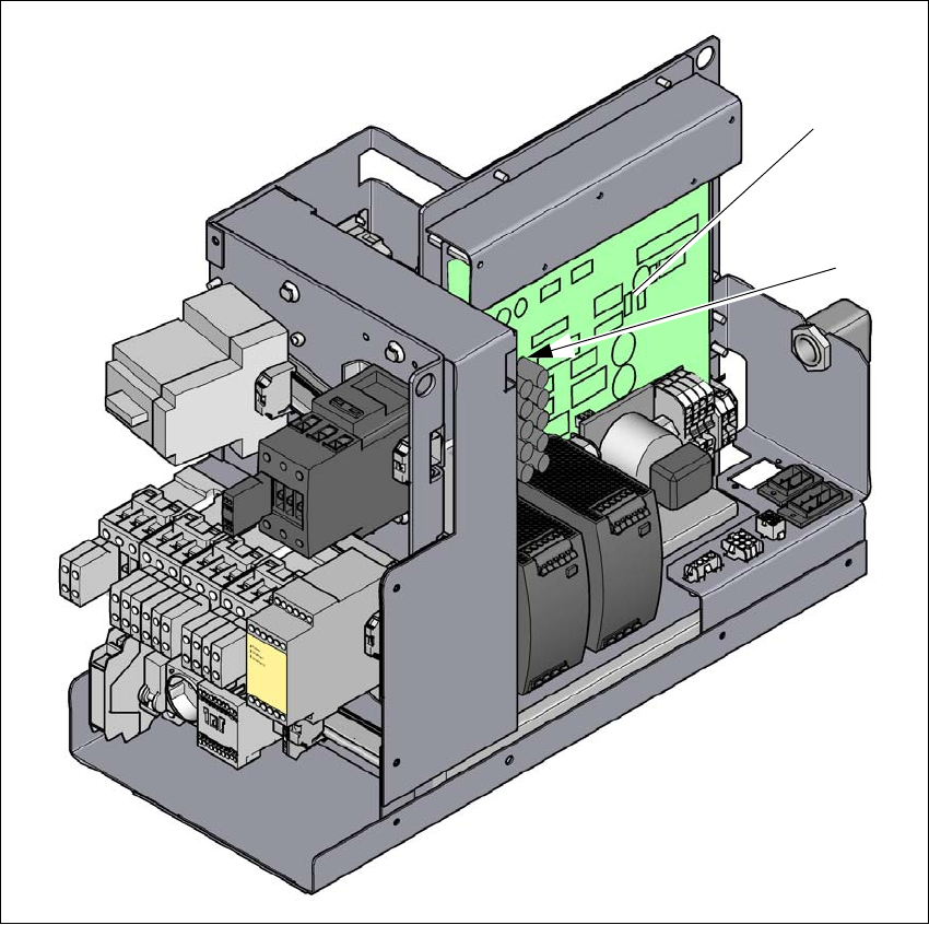
Fig. 2.8 - 2 Measuring points on the power supply unit
(1) Fuse and distributor board (A3)
(2) Rectifier board (A7)
(1)
(2)