00196457-05_UM_SX12DX12_SR706_EN.pdf - 第218页
4 Setting up and commissioning User Manual SIPLACE SX1/SX2/DX1/DX2 4.3 Setting up the machine From software version SC.706.xx Version 06/2012 EN 218 4.3 Setting up the machine 4.3.1 W arning instructions DANGER 4 Only SI…
User Manual SIPLACE SX1/SX2/DX1/DX2 4 Setting up and commissioning
From software version SC.706.xx Version 06/2012 EN 4.2 Infrastructure at the installation location
217
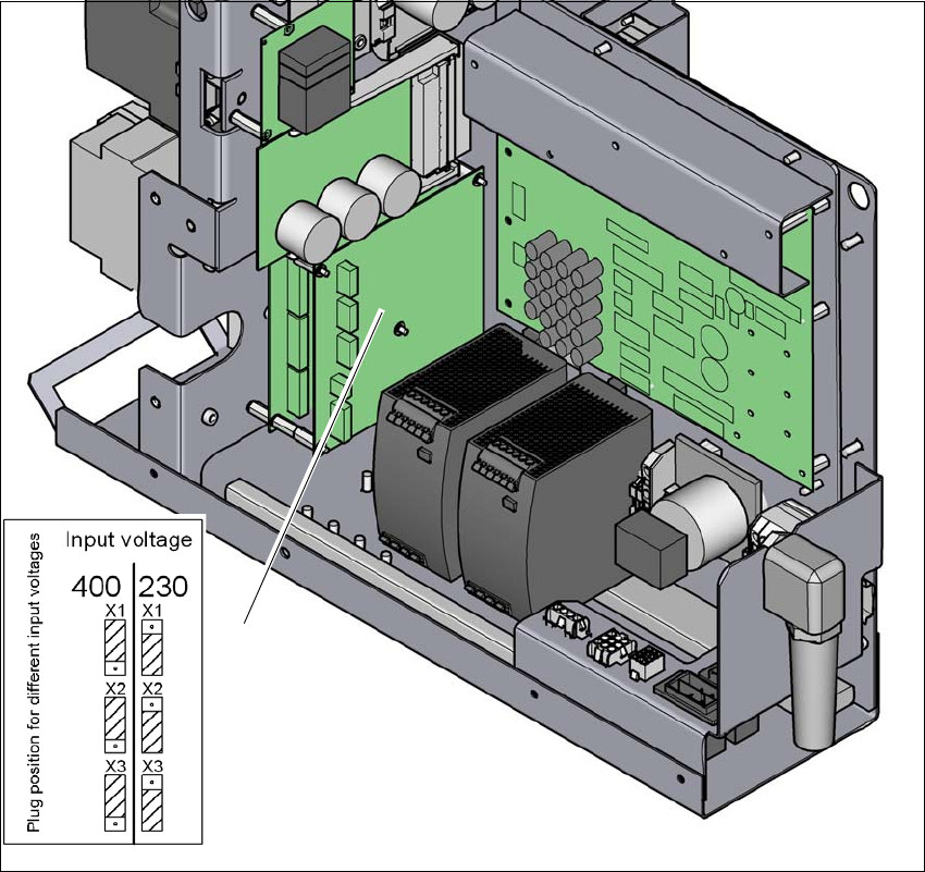
4.2.3.7 Checking the inrush current limitation jumpers
The inrush current limiter of the transformer (A1) is connected in the same manner for all supply
voltages. The connectors must all be plugged into the position for input voltage 230V.
4
Fig. 4.2 - 7 Position of the board and connectors for the inrush current limitation
(1) Inrush current limiter for transformer (A1)
(2) Configuration schema
Check the connector assignment for the inrush current limiter of the transformer. The connec-
tors for all mains voltages need to be plugged into the Input Voltage 230V point.
(1)
(2)

4 Setting up and commissioning User Manual SIPLACE SX1/SX2/DX1/DX2
4.3 Setting up the machine From software version SC.706.xx Version 06/2012 EN
218
4.3 Setting up the machine
4.3.1 Warning instructions
DANGER 4
Only SIPLACE engineers or qualified people are permitted to set up and commission the machine.
Always follow the applicable accident prevention regulations.
If you still need to perform assembly work to the underside of the machine, take appropriate
measures to secure the machine first. The fork-lift must not be used as the only support.
Make sure that the gantries are positioned over the PCB conveyor area so that you do not
restrict your head movement during assembly, thus excluding the risk of injury.
Two people will be needed to adjust the height of the machine:
– One person to carry out the necessary assembly work and the other person to watch the
watch the raised machine during assembly and ensure that it does not move.
Wear special safety boots to protect your feet.
User Manual SIPLACE SX1/SX2/DX1/DX2 4 Setting up and commissioning
From software version SC.706.xx Version 06/2012 EN 4.3 Setting up the machine
219
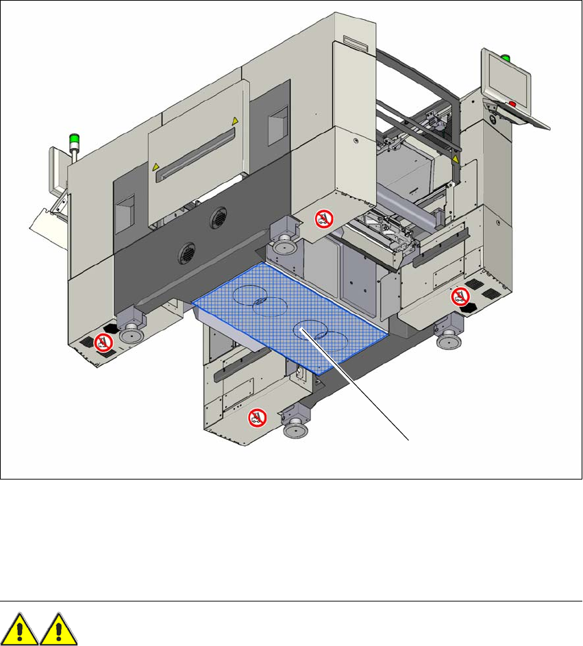
4.3.2 Lifting and transporting the machine with the fork lift truck
4
Fig. 4.3 - 1 Contact surface - forks at right angles to the direction of PCB transport (example of SX1/SX2)
(1) Contact surface for fork lift truck forks
Position the fork-lift truck at right angles to the PCB conveyor and open the forks until the con-
tact surfaces of the machine lie evenly on the forks.
WARNING 4
Please note the following points before you raise the machine in order to avoid irreversible dam-
age to the machine:
Please note the following points before you raise the machine in order to avoid irreversible dam-
age to the machine:
– The forks must be aligned parallel to the PCB conveyor.
– The forks must be aligned to the center of the machine.
– The forks may only be opened to a degree which ensures that they are still within the contact
(1)