00196457-05_UM_SX12DX12_SR706_EN.pdf - 第18页
1 Introduction User Manual SIPLACE SX1/SX2/DX1/DX2 1.2 SIPLACE DX1/DX2 From software version SC.706.xx Version 06/2012 EN 18 1.2 SIPLACE DX1/DX2 1 Fig. 1.2 - 1 SIPLACE DX1/DX2 placement machine The SIPLACE DX1 and DX2 pl…

User Manual SIPLACE SX1/SX2/DX1/DX2 1 Introduction
From software version SC.706.xx Version 06/2012 EN 1.1 SIPLACE SX1/SX2
17
The SIPLACE SX1 placement machine consists of one gantry while the SIPLACE SX2 placement
machine has two gantries. The head and gantry modularity principle developed by SIPLACE al-
lows you to change placement heads and gantries quickly and easily. For an overview of the
placement head configuration, refer to section 1.1.1
from page 17.
These can be quickly and accurately positioned by linear motors, moving independently of one
another in the X and Y directions.
The SX1/SX2 machine supports use of either the SIPLACE single conveyor or the flexible dual
conveyor.
There are two locations available for supplying components. These can be fitted with component
trolleys and configured with up to 60 tracks.
Alternatively, you can also dock a waffle pack changer (WPC5 or WPC6) at each of the two loca-
tions. If a WPC5/WPC6 is set up at one of the locations, a component trolley with 30 tracks must
be configured for the other location.
1.1.1 Overview of placement head configuration
1
Machine Placement head Standard cameras Options
SIPLACE
SX1
C&P20 Component camera, type
23
–none
CPP Component camera, type
30
– Stationary camera, type 33
TH Component camera, type
33
– Stationary camera, type 25 (only
at location 1)
SIPLACE
SX2
C&P20 / C&P20 Component camera, type
23
–none
CPP / CPP
Component camera, type
30
– Stationary camera, type 33
CPP / Twin Head
Component camera, type
30
Stationary camera, type 33
– Stationary camera, type 25 (only
at location 1)
Twin Head / Twin Head
Stationary camera, type 33 – Stationary camera, type 25 (only
at location 1)
1 Introduction User Manual SIPLACE SX1/SX2/DX1/DX2
1.2 SIPLACE DX1/DX2 From software version SC.706.xx Version 06/2012 EN
18
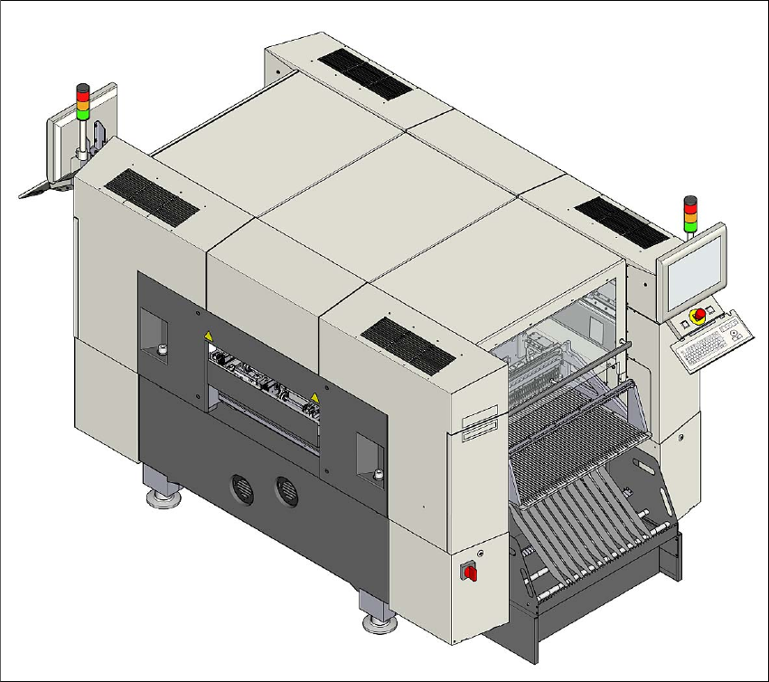
1.2 SIPLACE DX1/DX2
1
Fig. 1.2 - 1 SIPLACE DX1/DX2 placement machine
The SIPLACE DX1 and DX2 placement machines have the following distinguishing features:
– High precision,
– Intelligent placement optimization,
– Intelligent configuration strategies and
– A wide ranging component spectrum from 01005 components to a size of
110 mm x 10 mm.
Two placement methods are possible for processing the components:
– Collect&Place and
– Pick&Place.

User Manual SIPLACE SX1/SX2/DX1/DX2 1 Introduction
From software version SC.706.xx Version 06/2012 EN 1.2 SIPLACE DX1/DX2
19
The SIPLACE DX1 placement machine consists of one gantry while the SIPLACE DX2 placement
machine has two gantries. For an overview of the placement head configuration, refer to section
1.1.1
from page 17.
These can be quickly and accurately positioned by linear motors, moving independently of one
another in the X and Y directions.
The SX1/SX2 machine supports use of either the SIPLACE single conveyor or the flexible dual
conveyor.
There are two locations with DX tables or optional DX changeover tables, available for supplying
components. These can be configured with up to 60 tracks.
Alternatively, you can also dock a waffle pack changer (WPC5 or WPC6) at each of the two loca-
tions. If a WPC5/WPC6 is set up at one of the locations, a DX table with 30 tracks must be con-
figured for the other location.