00196457-05_UM_SX12DX12_SR706_EN.pdf - 第73页
User Manual SIPLACE SX1/SX2/DX1/DX2 2 Operational safety From software version SC.706.xx Version 06/2012 EN 2.7 Safety equipment 73 2.7.3 Position of protective cont actor combination and service socket 2 Fig. 2.7 - 6 Po…

2 Operational safety User Manual SIPLACE SX1/SX2/DX1/DX2
2.7 Safety equipment From software version SC.706.xx Version 06/2012 EN
72
Component counter 2
The number of placed components (component counter) can be read on the station software. For
more information, refer to the Online Help.
EMERGENCY STOP button with forced locking (item 5 in fig. 2.7 - 3, page 68 and item 1 in fig.
2.7 - 4, page 69) 2
The EMERGENCY STOP button is red and latches in the ON position when pressed. When you
press the EMERGENCY STOP button, the switching contact of the EMERGENCY STOP circuit
opens and the protective contactor combination (K3) trips. The link voltage (260 VDC) for the gan-
try axes and the link voltage (150 VDC) for the star axes is switched off. The servo amplifiers for
the DP and Z axes are still supplied with 42 VDC. The signaling contact of the EMERGENCY
STOP button opens and the message "EMERGENCY STOP pressed" appears on the screen.
The following modules are deactivated:
– PCB conveyor
– PCB clamping
– Width adjustment
– PCB stopper
– Feeder Control Unit
– Safety valve for the tape cutter
PLEASE NOTE
Placement is interrupted and can then either be continued or canceled once the machine is work-
ing correctly again. 2
Protective cover switch 1 and 2 ( item 1 and 2 in fig. 2.7 - 5, page 70) 2
These switches check whether the protective covers are closed. When they are closed, the
EMERGENCY STOP contact and the signaling contact are closed. If one of the covers is opened,
the EMERGENCY STOP contact and the signaling contact will open. Individual components are
disabled or remain enabled (see fig. 2.7 - 8
, page 77 ).
Protective switch for bumper detection ( item 3 in fig. 2.7 - 5, page 70) (SX1/SX2 only) 2
In SIPLACE SX1/SX2 machines, this switch checks whether at least one bumper is present. This
ensures that at least one bumper has been installed again after gantry replacement.
User Manual SIPLACE SX1/SX2/DX1/DX2 2 Operational safety
From software version SC.706.xx Version 06/2012 EN 2.7 Safety equipment
73
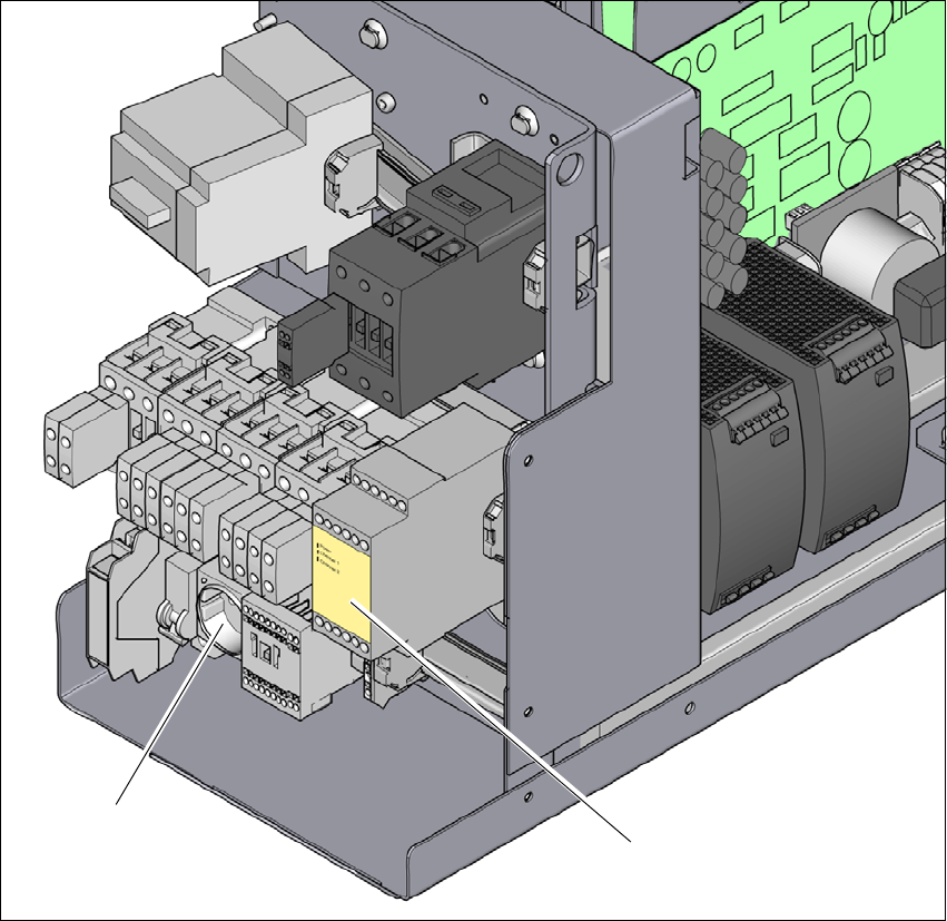
2.7.3 Position of protective contactor combination and service socket
2
Fig. 2.7 - 6 Position of protective contactor combination and service socket
2
(1) Protective contactor combination
(2) Service socket
(2)
(1)
2 Operational safety User Manual SIPLACE SX1/SX2/DX1/DX2
2.7 Safety equipment From software version SC.706.xx Version 06/2012 EN
74
Protective contactor combination K3 ( item 1 in fig. 2.7 - 6, page 73) 2
The protective contactor combination is contained in the power supply unit. It is used to monitor
the EMERGENCY STOP circuits and safety equipment.
There are three conditions that must be fulfilled in order to activate the protective contactor com-
bination:
– The "software release" or "Control ON" signal must be issued.
– The EMERGENCY STOP loop must be closed.
– The start button must have been pressed.
The front side of the protective contactor combination has three green LEDs for the operating dis-
play (see fig. 2.7 - 7
, page 75 )
– The "Power" LED indicates that voltage is present.
– The "Channel 1" and "Channel 2" LEDs shine if the start button has been pressed, the EMER-
GENCY STOP circuit is closed and the signaling circuit has not indicated any error states.
Service socket ( item 2 in fig. 2.7 - 6, page 73) 2
The service socket is contained in the power supply unit and is protected by the cover. It can only
be used if the machine is connected to the main power supply via a 5-wire connection (L1, L2, L3,
N, and PE). If a 4-wire connection is used, e.g. without N, the socket cannot be used.
WARNING 2
Always follow the safety instructions concerning potentially lethal voltages - even when the
machine is switched off. (see section 2.1.3 from page 36)