00196457-05_UM_SX12DX12_SR706_EN.pdf - 第141页
User Manual SIPLACE SX1/SX2/DX1/DX2 3 Technical data and assemblies From software version SC.706.xx V ersion 06/2012 EN 3.7 Gantry system 141 3.7.2 Structure of the X axis 3 Fig. 3.7 - 2 Design of X axis - view of head m…
3 Technical data and assemblies User Manual SIPLACE SX1/SX2/DX1/DX2
3.7 Gantry system From software version SC.706.xx Version 06/2012 EN
140
3.7 Gantry system
The gantry system of the SIPLACE SX1/SX2/DX1/DX2 machines is a so-called H gantry. This
consists of two Y axes which are driven from both sides by linear motors. The X axis is driven by
one linear motor. The H gantry runs over a fixed and a loose bearing along the bearing surface of
the two Y axes. These surfaces are at an angle of 45° to the gantry. The linear scales for the Y
measuring system are located under these bearing surfaces. In the SIPLACE SX/DX, the gantries
have the same design. This machine can be equipped with either one or two gantries. The SI-
PLACE SX2/DX2 has gantries 1 and 2 which are fitted at an angle of 180°. The placement heads
are fitted to the inside of the gantry.
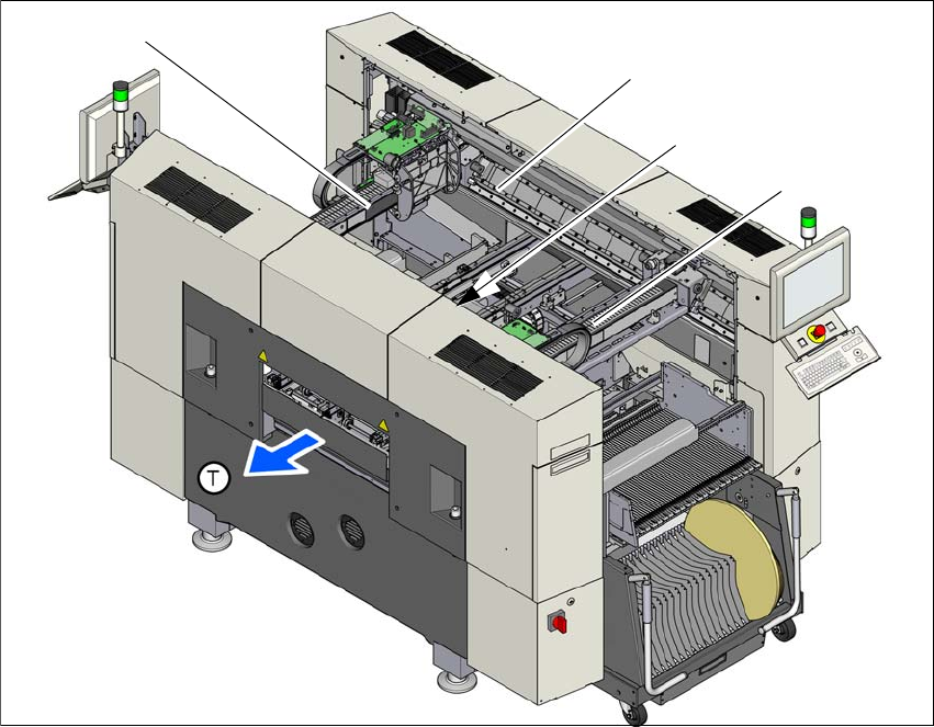
3.7.1 Position of the gantries
3
Fig. 3.7 - 1 Position of gantries in the SX2 machines
(1) X axis, gantry 1
(2) Y axis, gantry 1 and gantry 2
(3) Y axis, gantry 1 and gantry 2 (concealed)
(4) X axis, gantry 2
(T) Direction of PCB transport
(1)
(2)
(4)
(3)
User Manual SIPLACE SX1/SX2/DX1/DX2 3 Technical data and assemblies
From software version SC.706.xx Version 06/2012 EN 3.7 Gantry system
141
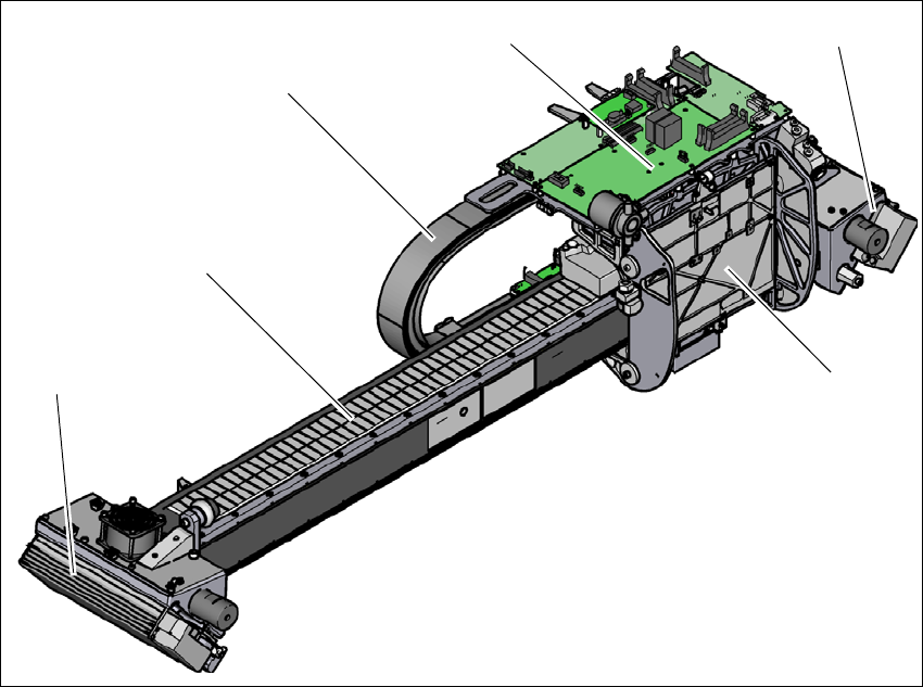
3.7.2 Structure of the X axis
3
Fig. 3.7 - 2 Design of X axis - view of head mount
(1) Head mount with X-axis linear motor (primary part)
(2) Y linear motor 2 with fixed bearing (primary part) and fan
(3) Guidance system with permanent magnet (secondary part of the X linear motor)
(4) Cable and hose carrier
(5) Head board with Head Control Unit
(6) Y linear motor 1 with loose bearing (primary part) and fan
(4)
(3)
(1)
(5)
(2)
(6)
3 Technical data and assemblies User Manual SIPLACE SX1/SX2/DX1/DX2
3.7 Gantry system From software version SC.706.xx Version 06/2012 EN
142
3
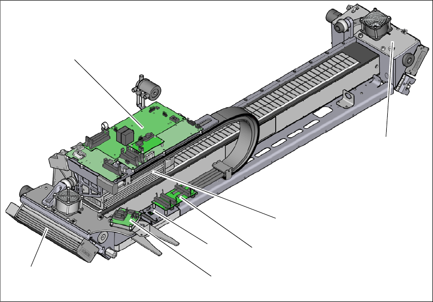
Fig. 3.7 - 3 Design of X axis - view of head mount
(1) Y linear motor 1 with loose bearing (primary part) and fan
(2) Head board with Head Control Unit
(3) Y linear motor 2 with loose bearing (primary part) and fan
(4) X axis linear motor (primary part)
(5) Gantry interface X axis
(6) Gantry interface Y axis
(7) Sensor module
(2)
(1)
(3)
(4)
(5)
(7)
(6)