00196457-05_UM_SX12DX12_SR706_EN.pdf - 第351页
User manual SIPLACE SX1/SX2/DX1/DX2 6 Station exte nsions From software version SC.706.xx V ersion 06/2012 EN 6.7 SIPLACE High-Force Head 351 6.7 SIPLACE High-Force Head Item no. 001 19736-xx High-Force Head This item nu…
6 Station extensions User manual SIPLACE SX1/SX2/DX1/DX2
6.6 Sensor for the component reject bin From software version SC.706.xx Version 06/2012 EN
350
6.5.4 Warning label 206
6
– W206 in fig. 6.5 - 4, page 349, item no. 03009345-01
– 1x on the docking station for SIPLACE SX component trolley
– 3 x on the covers for the energy supply.
6.6 Sensor for the component reject bin
Item no. 00519848-xx query for component reject bin
The sensor for the component reject bin monitors whether the reject bin is seated correctly in its
mount.
– If the reject bin was not inserted correctly, the machine cannot be started.
– If the reject bin jumps out of its mount during the placement process, the machine is stopped
immediately to avoid a head crash.
Each reject bin can be monitored by a separate sensor.
PLEASE NOTE 6
When using a SpeedStar we recommend that you install the optional sensor for the component
reject bin.
DANGEROUS VOLTAGES!
The labeled parts are still live when the main power switch is off.
Disconnect the machine from the mains before servicing it.
NAFTA region: RISK OF ELECTRIC SHOCK OR BURN!

User manual SIPLACE SX1/SX2/DX1/DX2 6 Station extensions
From software version SC.706.xx Version 06/2012 EN 6.7 SIPLACE High-Force Head
351
6.7 SIPLACE High-Force Head
Item no. 00119736-xx High-Force Head
This item number only applies when ordering a new placement machine with a high force
head instead of a standard TwinStar. 6
6.7.1 Description
The SIPLACE high force head is an advanced development of the standard TwinStar. It can pro-
cess the same component range and also offers the possibility of achieving set-down forces up to
30 N. The SIPLACE high force head can use all the same nozzles and grippers as the standard
TwinStar.
6.7.2 Technical data
6
Al other technical data are identical for the TwinStar and high force head (see section 3.6.3.2,
page 135
).
Programmable set-down force 2.0 N to 10 N ± 10 %
greater than 10 N up to 30 N ± 15 %
6 Station extensions User manual SIPLACE SX1/SX2/DX1/DX2
6.8 Component camera for the TwinStar, FC camera From software version SC.706.xx Version 06/2012 EN
352
6.8 Component camera for the TwinStar, FC camera
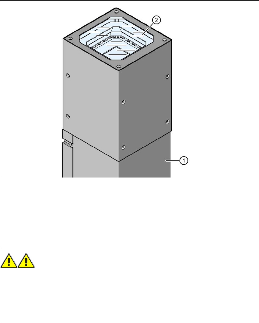
6.8.1 Stationary P&P component camera (type 25) 16 x 16, digital (FC camera)
Item no. 00119718-xx Stationary component camera 16x16 digital, type 25
6
Fig. 6.8 - 1 Stationary P&P component camera (type 25) 16 x 16, digital (FC camera)
(1) Camera housing with integral camera and camera amplifier
(2) Glass plate - over the illumination and lens levels
6.8.2 Safety instructions
WARNING 6
When changing the placement head from TwinStar to SpeedStar, the stationary component cam-
eras of type 33, 55 x 45, digital, and type 25, 16 x 16, digital (FC camera) need to be dismantled
from the TwinStar, otherwise the SpeedStar will collide with the camera housing.
When changing the placement head from TwinStar to MultiStar, the stationary component cam-
era, type 33, 55 x 45, digital, is fitted in the bottom position.