00196457-05_UM_SX12DX12_SR706_EN.pdf - 第322页
6 Station extensions User manual SIPLACE SX1/SX2/DX1/DX2 6.1 Nozzle changer From software version SC.706.xx Version 06/2012 EN 322 6.1.3.3 Position of nozzle changer for the SIPLACE T winSt ar in the SX machine 6 Fig. 6.…

User manual SIPLACE SX1/SX2/DX1/DX2 6 Station extensions
From software version SC.706.xx Version 06/2012 EN 6.1 Nozzle changer
321
6.1.3.2 Technical data
6
6
Nozzle changer for the SIPLACE TwinStar
Dimensions (length x width x height) 314 mm x 68 mm x 49 mm
Number of nozzle holders max. 16 for standard nozzles
4 for special nozzles or grippers
Nozzle types 5xx, standard
4 xx with adapter
9 xx with adapter
Nozzle changeover time Approx. 2 s per nozzle
6 Station extensions User manual SIPLACE SX1/SX2/DX1/DX2
6.1 Nozzle changer From software version SC.706.xx Version 06/2012 EN
322
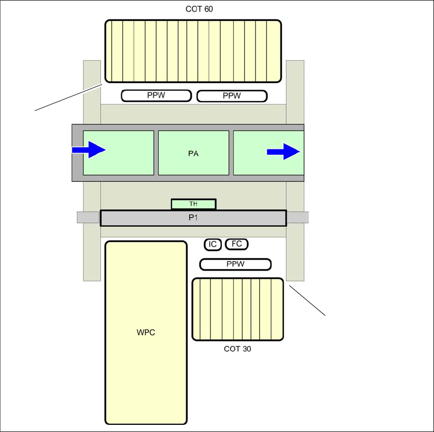
6.1.3.3 Position of nozzle changer for the SIPLACE TwinStar in the SX machine
6
Fig. 6.1 - 15 Position of nozzle changer for the SIPLACE TwinStar - example
6
(1) Component trolley in the inner position
(2) Component trolley in the outer position
PPW) Nozzle changer
(PA) Placement area
(1)
(2)
User manual SIPLACE SX1/SX2/DX1/DX2 6 Station extensions
From software version SC.706.xx Version 06/2012 EN 6.1 Nozzle changer
323
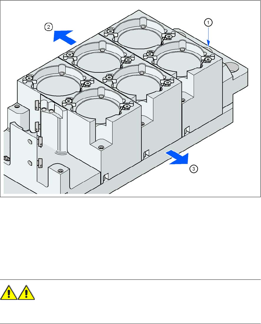
6.1.3.4 Assembly
The nozzle changer is fixed to the component trolley docking unit.
6
Fig. 6.1 - 16 Assembly position
(1) Marking hole
(2) Operator side
(3) Arrow pointing toward the PCB conveyor
6
Align the nozzle changer so that the marking hole (item 1) is on the left, as viewed by the op-
erator.
WARNING 6
Only install the associated nozzle changer for each placement head, with the nozzle magazines
for the respective placement head. There is a risk of head crashes with mixed configurations.