00196457-05_UM_SX12DX12_SR706_EN.pdf - 第294页
5 Working with the machine User Manual SIPLACE SX1/SX2/DX1/DX2 5.13 Avoiding track errors From softwar e version SC.706.xx Version 06/2012 EN 294 5.13 A voiding track errors 5.13.1 General Make sure that the areas arou…

User Manual SIPLACE SX1/SX2/DX1/DX2 5 Working with the machine
From software version SC.706.xx Version 06/2012 EN 5.12 Changing the setup
293
5.12 Changing the setup
5.12.1 Printing out the conversion instructions before changing the setup
Before a change of setup, print out the conversion instructions on the printer for the SIPLACE Pro
computer as described in the "SIPLACE Pro" manual or in the online help.
5.12.2 What you should note when changing the feeder modules
Handle the feeder modules carefully when you insert them into or remove them from the
changeover table. Make sure that the X feeder modules do not bump against the centering
bar (see item 5 in fig. 5.10 - 3
, page 281) of the changeover table.
Vacuum the supporting surfaces of the feeder modules and clean the surface of the change-
over table when necessary according to the instructions in the preventive maintenance man-
ual.
Remove loose components using a brush or a vacuum cleaner with a suitable nozzle.
CAUTION 5
Avoid removing components from the changeover table with your fingers. You may hurt your-
self
with tiny splinters of metal.

5 Working with the machine User Manual SIPLACE SX1/SX2/DX1/DX2
5.13 Avoiding track errors From software version SC.706.xx Version 06/2012 EN
294
5.13 Avoiding track errors
5.13.1 General
Make sure that the areas around the feeder modules are clean and that there are no loose
components in the feeder area or under the feeder modules.
Refill promptly with components.
Splice the tapes early. This generally means that you are to prepare the splicing material
when there is still approximately 1.5 m of tape on the reel.
Handle the feeder modules carefully when you insert them into or remove them from the
changeover table as these are high-precision devices.
For X feeder modules, lower the pickup window since it can easily be damaged when raised.
PLEASE NOTE 5
A raised pick-up window leads to noticeably impaired pick-up quality.
Check that the pick-up position is set correctly for the components on the feeder modules.
5.13.2 Avoiding track errors with the tape container
Insert the separating plates correctly (see fig. 5.9 - 3, page 276).
User Manual SIPLACE SX1/SX2/DX1/DX2 5 Working with the machine
From software version SC.706.xx Version 06/2012 EN 5.13 Avoiding track errors
295
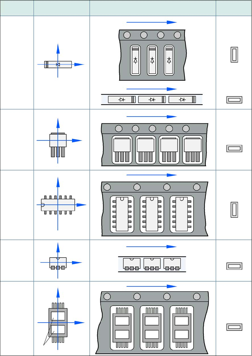
5.13.3 Component coordinate system and pickup angle
5
Fig. 5.13 - 1 Position of the component and its pick-up angle
Special
component
Stick
magazine:
Chip-
components
with polarity
0402
2220
The anode must be
aligned with the +X
coordinate.
Package form Coordinate system
Position in the feeder module
Pickup angle/
nozzle angle
Tape:
SOT 23
Stick
magazine:
Tape:
Tape:
SO-IC
DIL-IC
SOT 194
Tape:
Holes
Y
X
Y
X
Y
X
Y
X
Y
X
90°
90°
0°
90°
-90°
0°