00196457-05_UM_SX12DX12_SR706_EN.pdf - 第232页
4 Setting up and commissioning User Manual SIPLACE SX1/SX2/DX1/DX2 4.3 Setting up the machine From software version SC.706.xx Version 06/2012 EN 232 PLEASE NOTE: T o guarantee the handling accuracy of the machine spir it…
User Manual SIPLACE SX1/SX2/DX1/DX2 4 Setting up and commissioning
From software version SC.706.xx Version 06/2012 EN 4.3 Setting up the machine
231
4.3.9 Aligning the machine with the machine spirit level
4
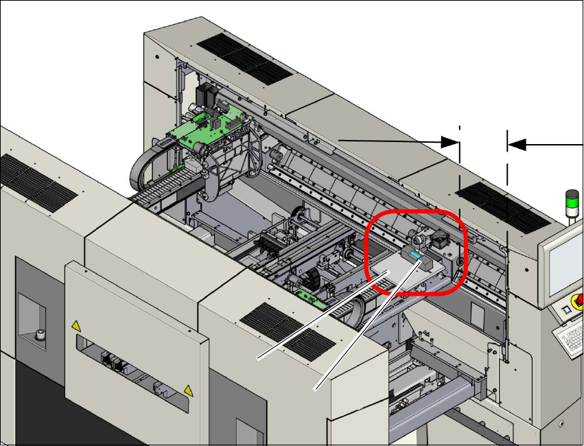
Fig. 4.3 - 8 Adjusting the machine in the X and Y directions - measurement (example of SX2)
Measurement is performed at gantry 1.
Push the gantry inwards, in the Y direction. The distance of the two bumpers should be ap-
prox. 300 mm (or approx. 4-5 red dots on the linear guide).
Place the support plate (1) onto the gantry so that the 3 support pins lie on the free areas be-
tween the running surface and the magnets. Make sure that the 3 support pins touch evenly.
Place the machine spirit level (measuring accuracy of 0.02 mm) onto the support plate and
measure at 3 points
– The alignment of the Y axis at the loose bearing side and at the fixed bearing side.
– The alignment of the X axis in the middle of the X gantry. The head mount must be in the
middle of the X gantry.
300 mm
(1)
(2)

4 Setting up and commissioning User Manual SIPLACE SX1/SX2/DX1/DX2
4.3 Setting up the machine From software version SC.706.xx Version 06/2012 EN
232
PLEASE NOTE:
To guarantee the handling accuracy of the machine spirit level, make sure that the spirit level is
always placed onto the support plate the same way round when measuring the X and Y directions.4
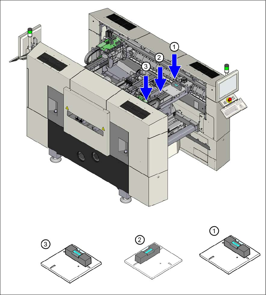
Adjust the machine by following the instructions below in the order listed:
(1) Align the machine in the Y direction at the fixed and loose bearing sides. The measuring tol-
erance is 0.10 mm.
(2) Align the machine in the X direction to the middle of the gantry. The measuring tolerance is
0.10 mm.
(3) Check the load-bearing strength of the 4 machine feet. The 4 machine feet must touch the
ground and be evenly loaded.
(4) Tighten the machine feet at the clamping screw to a torque of 130 Nm.
(5) Hit the feet with a hammer to check the load-bearing strength of the machine feet.
(6) Use the spirit level to ensure that the machine is precisely aligned.
User Manual SIPLACE SX1/SX2/DX1/DX2 4 Setting up and commissioning
From software version SC.706.xx Version 06/2012 EN 4.3 Setting up the machine
233
4
Fig. 4.3 - 9 Measuring points on the machine (example of SX1/SX2)