00196457-05_UM_SX12DX12_SR706_EN.pdf - 第118页
3 Technical data and assemblies Us er Manual SIPLACE SX1/SX2/DX1/DX2 3.6 Placement head From software version SC.706.xx Version 06/2012 EN 118 3.6 Placement head 3.6.1 SIPLACE SpeedSt ar C&P20 for very high speed pla…
User Manual SIPLACE SX1/SX2/DX1/DX2 3 Technical data and assemblies
From software version SC.706.xx Version 06/2012 EN 3.5 Overview of the assemblies
117
3.5.4 Overview of the SIPLACE DX1 assemblies
3
3
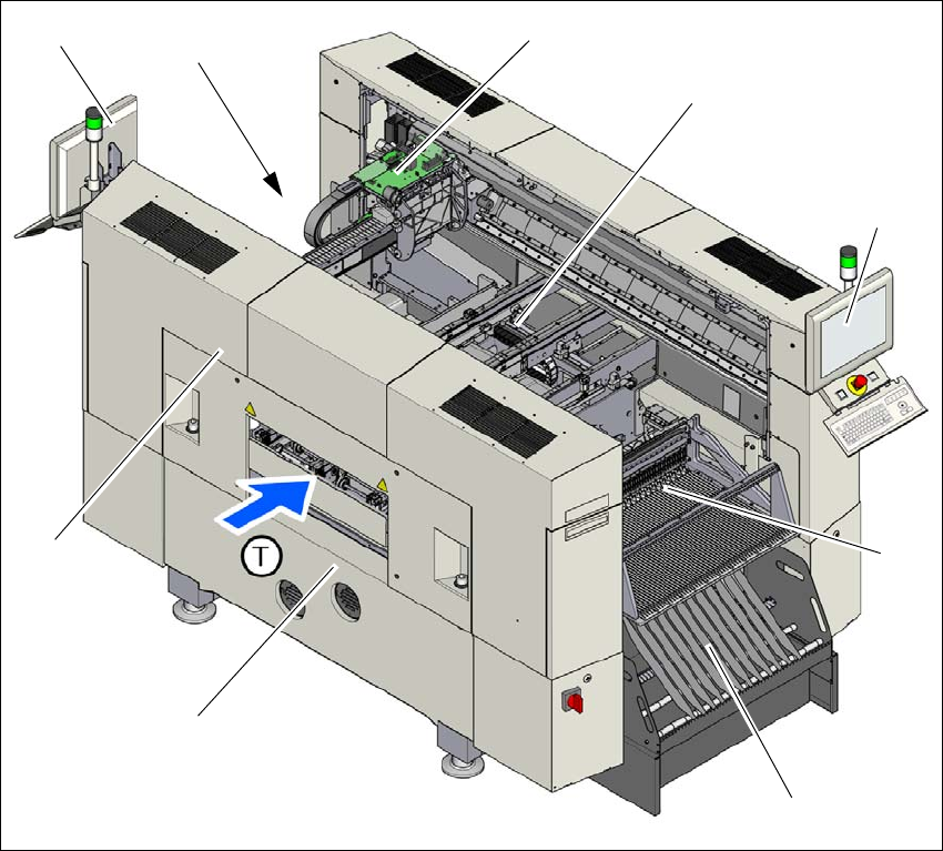
Fig. 3.5 - 4 DX1 machine - overview of assemblies
(1) Basic module
(2) Robot module
(3) Gantry 1 with placement head
(4) PCB conveyor (single or dual conveyor)
(5) Monitor with keyboard (2x)
(6) Tape container with waste tape container
(7) Location 2 with DX table, tape cutter, empty tape duct
(8) Location 1 with DX table, tape cutter, empty tape duct
(T) Direction of PCB transport
(1)
(2)
(3)
(4)
(5)
(6)
(5)
(8)
(7)
3 Technical data and assemblies User Manual SIPLACE SX1/SX2/DX1/DX2
3.6 Placement head From software version SC.706.xx Version 06/2012 EN
118
3.6 Placement head
3.6.1 SIPLACE SpeedStar C&P20 for very high speed placement
3
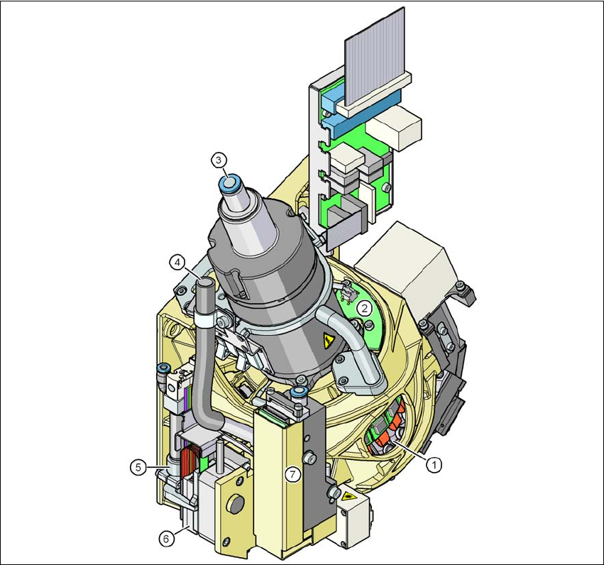
Fig. 3.6 - 1 SIPLACE SpeedStar - function group part 1
(1) DP drive, 20 drives
(2) "Vacuum sensor holding circuit" board
(3) Compressed air connection for 20 Venturi nozzles in the pick-up/placement and holding cir-
cuit
(4) Line for the exhaust air from the pressure control valve (7)
(5) Return cylinder
(6) Z motor (linear motor)
(7) Pressure control valve
User Manual SIPLACE SX1/SX2/DX1/DX2 3 Technical data and assemblies
From software version SC.706.xx Version 06/2012 EN 3.6 Placement head
119
3
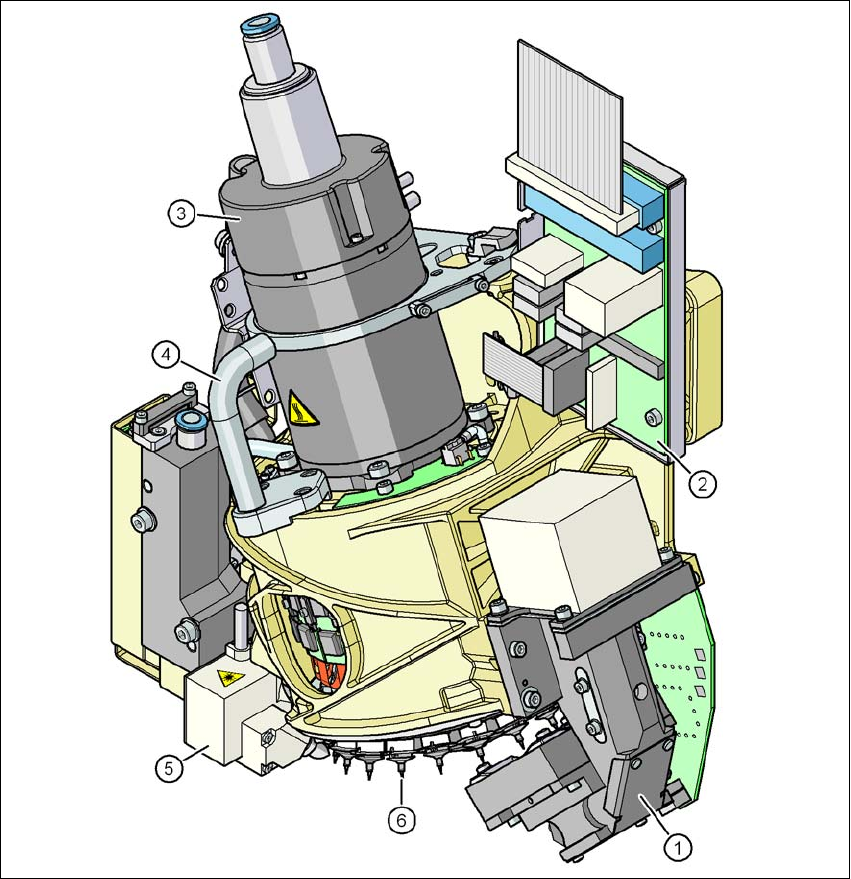
Fig. 3.6 - 2 SIPLACE SpeedStar - function group part 2
(1) C&P component camera, type 23, 6 x 6, digital
(2) Intermediate distributor board
(3) Star motor
(4) Handle
(5) Component sensor
(6) Star with 20 nozzles