00196457-05_UM_SX12DX12_SR706_EN.pdf - 第280页
5 Working with the machine User Manual SIPLACE SX1/SX2/DX1/DX2 5.10 Setting up the feeder modules From software version SC.706.xx Version 06/2012 EN 280 5 Fig. 5.10 - 2 Check the X feeder module before using it (1) Remov…

User Manual SIPLACE SX1/SX2/DX1/DX2 5 Working with the machine
From software version SC.706.xx Version 06/2012 EN 5.10 Setting up the feeder modules
279
PLEASE NOTE 5
Do not press the lever if a component tape is inserted. The tensioned cover foil would move
the component tape on and expose the components.
Remove any loose components from beneath the pick-up window.
Close the pickup window (item 3 in fig. 5.10 - 2), by returning the lever (item 4 in fig. 5.10
- 2) to its original position.
Remove loose components from the changeover table with a brush or use a vacuum
cleaner with appropriate nozzle.
PLEASE NOTE 5
If the component tape is already inserted, cut it off flush with the front edge of the feeder mod-
ule.
If the removal handle (item 1) is still protruding, then latch it in place.
5 Working with the machine User Manual SIPLACE SX1/SX2/DX1/DX2
5.10 Setting up the feeder modules From software version SC.706.xx Version 06/2012 EN
280
5
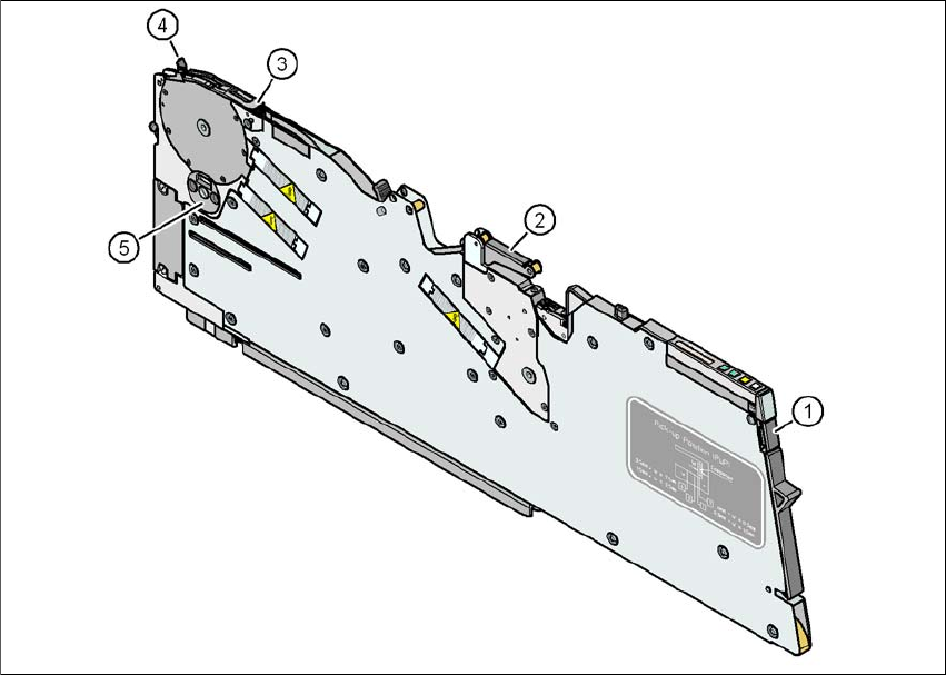
Fig. 5.10 - 2 Check the X feeder module before using it
(1) Removal handle
(2) Cover foil rocker
(3) Pickup window
(4) Lever for raising and latching the pick-up window
(5) Component disposal compartment
User Manual SIPLACE SX1/SX2/DX1/DX2 5 Working with the machine
From software version SC.706.xx Version 06/2012 EN 5.10 Setting up the feeder modules
281
5.10.3.2 Inserting the X feeder module into the changeover table
5
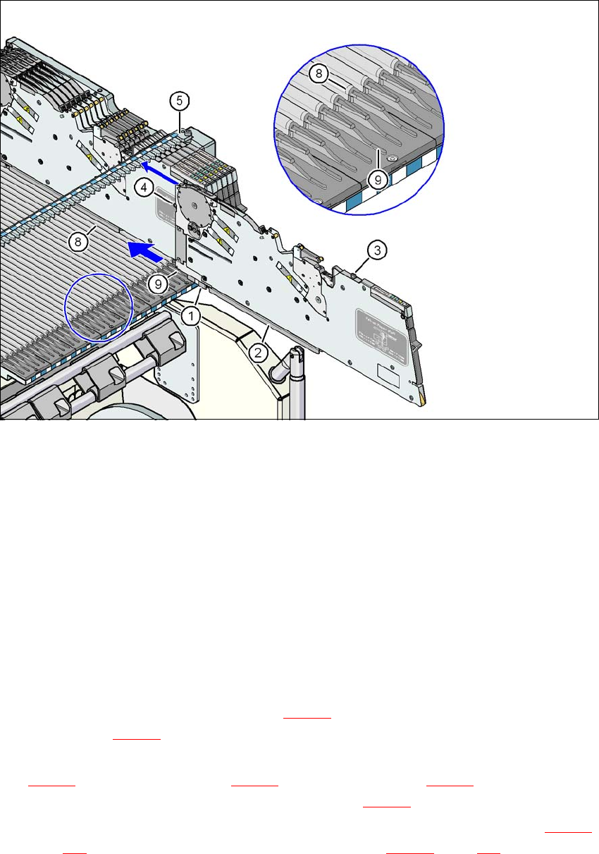
Fig. 5.10 - 3 Inserting the X feeder module into the changeover table
(1) Front slider guide for the X feeder module
(2) Back slider guide for the X feeder module
(3) "Back" centering pin on the X feeder module
(4) "Front" centering pin on the X feeder module
(5) Recesses in the centering bar for holding the "back" centering pin
(6) Centering holes on the changeover table for holding the "front" centering pin
(7) Locking latches
(8) Guide profile for the changeover table ( profile)
(9) Insertion aid for the feeder module
5
Place the front slider guide (item 1 in fig. 5.10 - 3) of the feeder module on the insertion aid
(item 9 in fig. 5.10 - 3
) of the changeover table.
Hold the feeder module vertically and push it forward, along the guide profile (item 8 in fig.
5.10 - 3
). The front (item 1 in fig. 5.10 - 3) and rear (item 2 in fig. 5.10 - 3) slider guides of the
feeder module slide on the guide profile (item 8 in fig. 5.10 - 3
).
Carefully push the feeder module further until the "front" centering pin (item 4 in fig. 5.10 - 3,
page 281
) is pushed into the centering hole (item 6 in fig. 5.10 - 3, page 281).