00196457-05_UM_SX12DX12_SR706_EN.pdf - 第68页
2 Operational safety User Manual SIPLACE SX1/SX2/DX1/DX2 2.7 Safety equipment From software version SC.706.xx Version 06/2012 EN 68 2.7.2 Switches and bu ttons on the machine 2.7.2.1 Position of switches and buttons on t…
User Manual SIPLACE SX1/SX2/DX1/DX2 2 Operational safety
From software version SC.706.xx Version 06/2012 EN 2.7 Safety equipment
67
Function 2
If the protective cover is swung upwards, the power supply to the gantry axes will be immediately
interrupted. The gantry axes stop moving. The message "Close cover" is displayed on the screen.
Close the protective covers and press the START button (item 1 in fig. 2.7 - 2), to continue
placement.
2
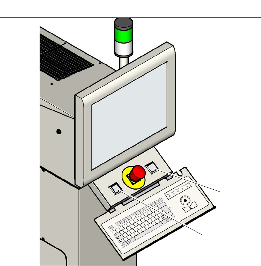
Fig. 2.7 - 2 Position of the start buttons (green) on the machine
(1) STOP button (black) on machine
(2) Start button (green) on the machine
(1)
(2)
2 Operational safety User Manual SIPLACE SX1/SX2/DX1/DX2
2.7 Safety equipment From software version SC.706.xx Version 06/2012 EN
68
2.7.2 Switches and buttons on the machine
2.7.2.1 Position of switches and buttons on the machine
2
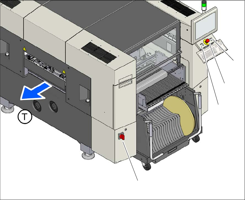
Fig. 2.7 - 3 Position of switches and buttons - View of the PCB output side (example of SX1/SX2)
(1) Main power switch
(2) Start button (green)
(3) EMERGENCY STOP button
(4) Stop button (black)
(T) PCB transport direction
(2)
(1)
(3)
(4)
User Manual SIPLACE SX1/SX2/DX1/DX2 2 Operational safety
From software version SC.706.xx Version 06/2012 EN 2.7 Safety equipment
69
2
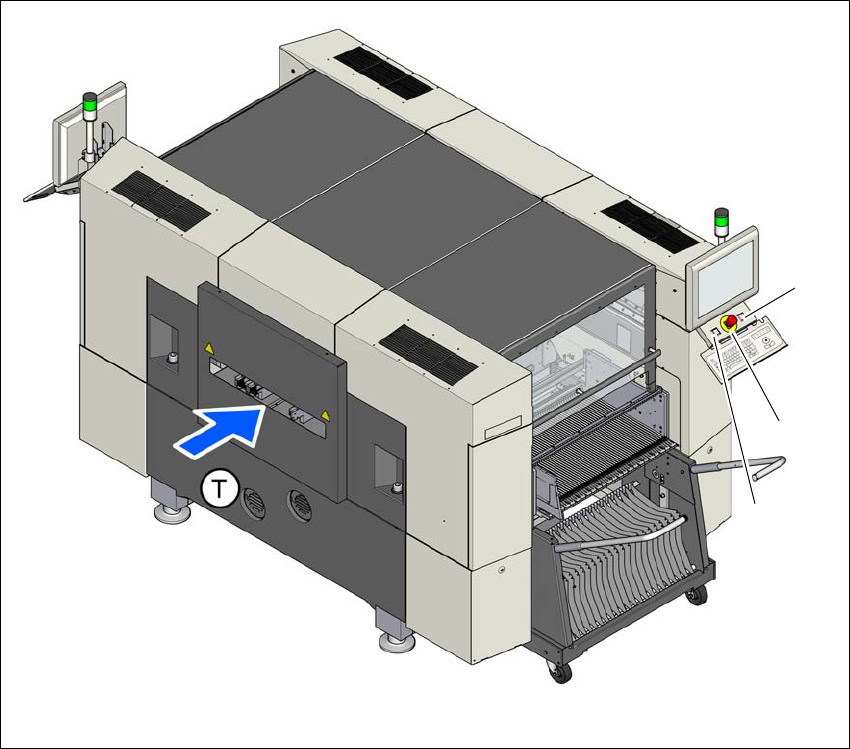
Fig. 2.7 - 4 Position of switches and buttons - View of the PCB input side (example of SX1/SX2)
(1) Start button (green)
(2) EMERGENCY STOP button
(3) Stop button (black)
(T) PCB transport direction
(3)
(1)
(2)