00196457-05_UM_SX12DX12_SR706_EN.pdf - 第140页
3 Technical data and assemblies Us er Manual SIPLACE SX1/SX2/DX1/DX2 3.7 Gantry system From software version SC.706.xx Version 06/2012 EN 140 3.7 Gantry system The gantry system of the SIPL ACE SX1/SX2/DX1/DX2 machines i…
User Manual SIPLACE SX1/SX2/DX1/DX2 3 Technical data and assemblies
From software version SC.706.xx Version 06/2012 EN 3.6 Placement head
139
3.6.4.2 Technical data
3
Optical centering with 12 segment Collect&Place head
with component camera, type 28
12 segment Collect&Place head
with component camera, type 30
Component range
a
a) Please note that the component range that can be placed is also affected by the pad geometry, the custom-
er-specific standards and the packaging tolerances.
0402 to PLCC44, BGA, µBGA, Flip-
Chip, TSOP, QFP, SO to SO32,
DRAM
0201
b
to Flip-Chip, Bare Die,
PLCC44, BGA, µBGA, TSOP, QFP,
SO to SO32, DRAM
b) with 0201 package
Component specification
max. height
min. lead pitch
min. lead width
min. ball pitch
min. ball diameter
min. dimensions
max. dimensions
max. weight
6 mm
0.5 mm
0.2 mm
0.35 mm
0.2 mm
1.0 x 0.5 mm²
18.7 x 18.7 mm²
2 g
6 mm
0.3 mm
0.15 mm
0.25 mm
0.14 mm
0.6 x 0.3 mm²
18.7 x 18.7 mm²
2 g
Programmable
set-down force
2.5 N to 5.0 N
Nozzle types 3 xx 3xx
X/Y accuracy
c
c) The accuracy value was measured using the vendor-neutral IPC standard.
± 45 μm / 3, ± 60 μm / 4 ± 41 µm/3± 55 µm/4
Angular accuracy ± 0.5°/3, ± 0.7°/4 ± 0.5°/3, ± 0.7°/4
Component range 98% 98.5%
Component camera type 28 30
Illumination level 5 5
Possible illumination level
settings
256
5
256
5
3 Technical data and assemblies User Manual SIPLACE SX1/SX2/DX1/DX2
3.7 Gantry system From software version SC.706.xx Version 06/2012 EN
140
3.7 Gantry system
The gantry system of the SIPLACE SX1/SX2/DX1/DX2 machines is a so-called H gantry. This
consists of two Y axes which are driven from both sides by linear motors. The X axis is driven by
one linear motor. The H gantry runs over a fixed and a loose bearing along the bearing surface of
the two Y axes. These surfaces are at an angle of 45° to the gantry. The linear scales for the Y
measuring system are located under these bearing surfaces. In the SIPLACE SX/DX, the gantries
have the same design. This machine can be equipped with either one or two gantries. The SI-
PLACE SX2/DX2 has gantries 1 and 2 which are fitted at an angle of 180°. The placement heads
are fitted to the inside of the gantry.
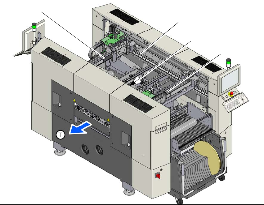
3.7.1 Position of the gantries
3
Fig. 3.7 - 1 Position of gantries in the SX2 machines
(1) X axis, gantry 1
(2) Y axis, gantry 1 and gantry 2
(3) Y axis, gantry 1 and gantry 2 (concealed)
(4) X axis, gantry 2
(T) Direction of PCB transport
(1)
(2)
(4)
(3)
User Manual SIPLACE SX1/SX2/DX1/DX2 3 Technical data and assemblies
From software version SC.706.xx Version 06/2012 EN 3.7 Gantry system
141
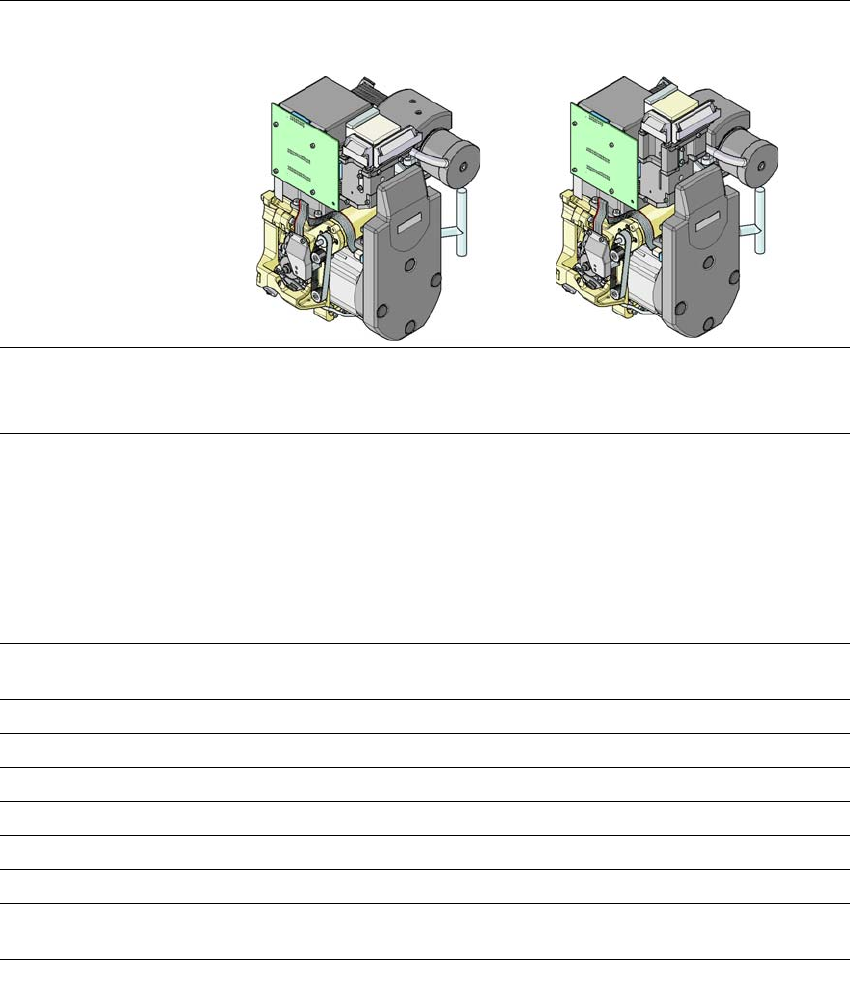
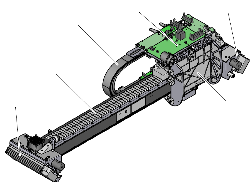
3.7.2 Structure of the X axis
3
Fig. 3.7 - 2 Design of X axis - view of head mount
(1) Head mount with X-axis linear motor (primary part)
(2) Y linear motor 2 with fixed bearing (primary part) and fan
(3) Guidance system with permanent magnet (secondary part of the X linear motor)
(4) Cable and hose carrier
(5) Head board with Head Control Unit
(6) Y linear motor 1 with loose bearing (primary part) and fan
(4)
(3)
(1)
(5)
(2)
(6)