00196457-05_UM_SX12DX12_SR706_EN.pdf - 第237页
User Manual SIPLACE SX1/SX2/DX1/DX2 4 Setting up and commissioning From software version SC.706.xx V ersion 06/2012 EN 4.4 Adjust ing the component trolley t o the PCB conveyor height 237 4.4.1 W arning instructions W AR…
4 Setting up and commissioning User Manual SIPLACE SX1/SX2/DX1/DX2
4.4 Adjusting the component trolley to the PCB conveyor height From software version SC.706.xx Version 06/2012 EN
236
4.4 Adjusting the component trolley to the PCB conveyor
height
The component trolley can be easily and quickly adjusted to the following PCB conveyor heights:
900 mm 4
930 mm (standard height) 4
950 mm (SMEMA height) 4
4
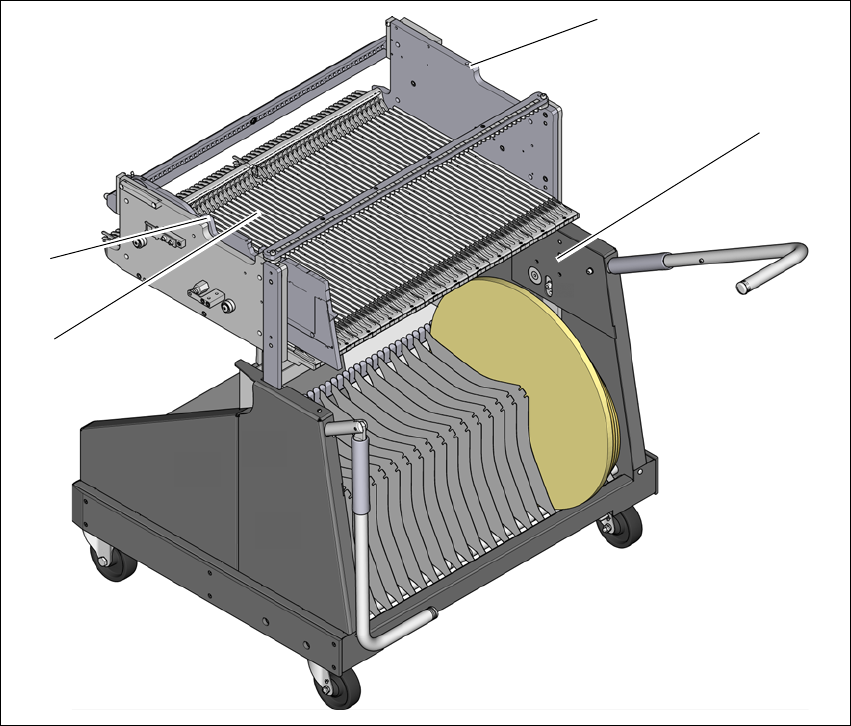
Fig. 4.4 - 1 Component trolley 60
(1) Holes for the transport heights of 900, 930 and 950 mm.
(2) changeover table
(3) M8 holes for fixing the mounting device
(1)
(2)
(3)
(3)

User Manual SIPLACE SX1/SX2/DX1/DX2 4 Setting up and commissioning
From software version SC.706.xx Version 06/2012 EN 4.4 Adjusting the component trolley to the PCB conveyor height
237
4.4.1 Warning instructions
WARNING 4
Only ASM engineers or qualified personnel are permitted to adjust the component trolley height.
Always follow the applicable accident prevention regulations.
Remove all the feeder modules from the changeover table, if you want to adjust the height for
the changeover table.
4.4.2 Tools and equipment
You will need the following tools and equipment to adjust the height of the component trolley:
– Mounting device (item no. 03015976-xx)
– Lifting device for raising the component trolley table, carrying capacity at least 80 kg
4.4.3 Changing the component trolley height
WARNING 4
Remove all the feeder modules from the changeover table.
Fit the mounting device to the changeover table in order to adjust the height. This prevents
the changeover table becoming deformed when the table is raised or lowered.
Fix the fit-up aid to the changeover table with the two M8 x 50 hexagon socket head screws.
There are two different holes available for the changeover table 60 and the changeover table
30.
Hook the leverage device into the eyelet.
Loosen the fastening screws and lift the changeover table into the required position.
Fit and tighten the fastening screws.
4 Setting up and commissioning User Manual SIPLACE SX1/SX2/DX1/DX2
4.5 Adjusting the empty tape duct to the component height From software version SC.706.xx Version 06/2012 EN
238
4.5 Adjusting the empty tape duct to the component
height
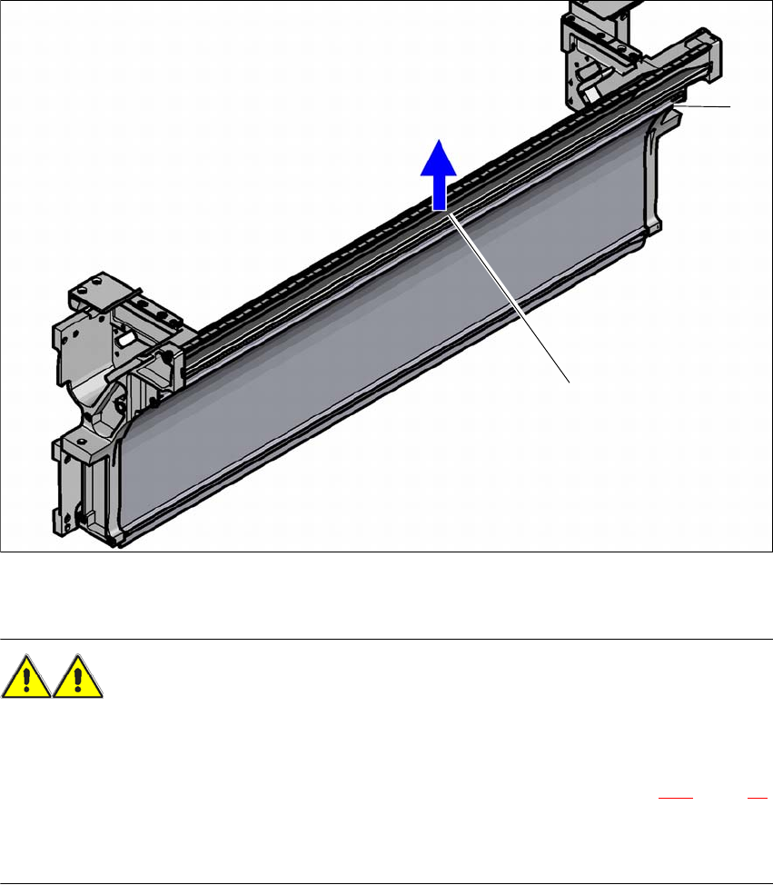
If feeder modules which use tapes with a pocket height of > 12 mm are used, remove the sepa-
rating plate (1).
4
(1) separating plate for tapes > 12 mm, removable
(2) Fastening screws
WARNING 4
Switch the machine off at the main switch to remove the dividing plate.
Disconnect the machine from the power and compressed air supply.
Lock the machine to prevent unauthorized reactivation, as described in section 2.11, page 89.
Wait until the operating pressure for the tape cutter has dropped to 0 MPa.
Do not reach inside the empty tape duct.
Loosen the fastening screws.
Pull out the separating plate.
(1)
(2)