00196457-05_UM_SX12DX12_SR706_EN.pdf - 第208页
4 Setting up and commissioning User Manual SIPLACE SX1/SX2/DX1/DX2 4.1 Transportation and Delivery Configuration F rom software version SC.706.xx Version 06/2012 EN 208 4 Fig. 4.1 - 4 Contact surfaces - forks parallel to…
User Manual SIPLACE SX1/SX2/DX1/DX2 4 Setting up and commissioning
From software version SC.706.xx Version 06/2012 EN 4.1 Transportation and Delivery Configuration
207
4.1.5.2 Means of transport
Use a fork-lift truck with the following specification to carry the machine:
4.1.5.3 Fork-lift attachment points on the machine
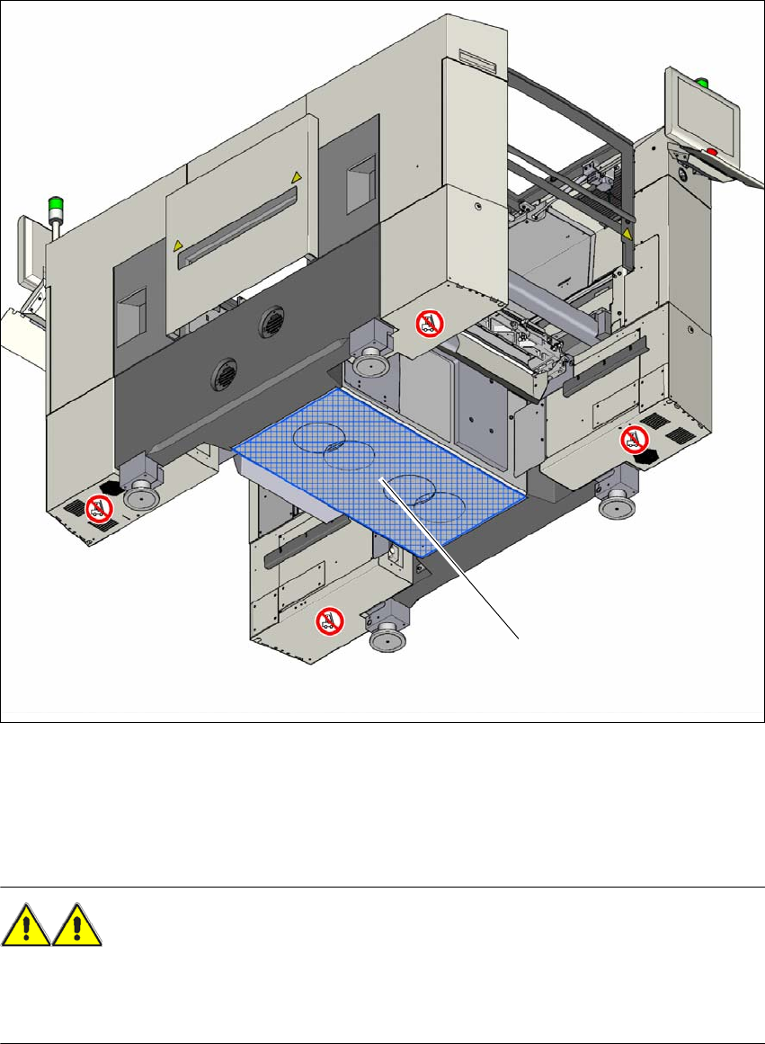
The diagram 4.1 - 4, page 208 shows the fork lift attachment points on the machine for lifting the
machine off the pallet or transporting it without the pallet.
PLEASE NOTE 4
Always use a pallet and fork-lift to transport the machine over longer distances in order to avoid
damaging the machine.
WARNING 4
Please note the following points before you raise the machine in order to avoid irreversible dam-
age to the machine:
– The forks must be aligned parallel to the PCB conveyor.
– The forks must be aligned to the center of the machine.
– The forks may only be opened to a degree which ensures that they are still within the contact
area of the machine underside (see fig. 4.1 - 4
, page 208).
– Do not increase the distance between the forks so that the machine is lifted outside this con-
tact surface. This would lead to deformation of the machine frame and/or damage to the ca-
bles and leads.
Make sure that the forks are evenly loaded when you lift the machine. A firm support between
the forks and machine will prevent the machine tilting when it is raised. This will also prevent
a one-sided load on the machine feet, which would deform the fixing of the machine feet. We
recommend that a second person watch the machine as it is raised, and make sure that the
machine does not tip to one side when lifted with the fork-lift.
Fork length min. 1800 mm
Lifting power min. 6000 kg
Distance between forks with the forks running parallel
to the direction of PCB transport
Approx. 420 mm
4 Setting up and commissioning User Manual SIPLACE SX1/SX2/DX1/DX2
4.1 Transportation and Delivery Configuration From software version SC.706.xx Version 06/2012 EN
208
4
Fig. 4.1 - 4 Contact surfaces - forks parallel to the direction of PCB transport (example of SX1/SX2)
(1) Contact surface for fork lift truck forks
4.1.5.4 Points that MUST be noted when transporting the machine
WARNING 4
When you are transporting the machine, make sure that all the feet are clear of the floor. If they
are not clear, the feet will drag along the floor or bump into obstacles. This could damage the
machine feet and/or the foot fixtures.
(1)
User Manual SIPLACE SX1/SX2/DX1/DX2 4 Setting up and commissioning
From software version SC.706.xx Version 06/2012 EN 4.2 Infrastructure at the installation location
209
4.2 Infrastructure at the installation location
4.2.1 Recommendations for the foundation quality
The foundation on which the machine is installed must be firm and level, as dynamic forces could
cause vibrations when the machine is operated. The degree of vibration depends on the construc-
tion of the foundation. The following are suitable provided that the floor loading parameters, etc.,
are not exceeded:
– Reinforced concrete ceiling constructions, e.g. ceilings in production halls
– Reinforced concrete floor slabs, e.g. concrete floors in production halls without a basement
– Rooms with double floors, provided that a stable foundation is included in the space between
them. The same setup conditions apply to this intermediate foundation, which can be made
from steel girders or concrete.
4.2.1.1 Maximum ground levelness
The floor underneath the machine may not exceed an incline of 0.63%. This corresponds to an
incline of 5 mm over a distance of 800 mm (e.g. the width of a changeover table).
4.2.1.2 Machine weight and floor loading
the machine weight and floor loading values can be found in section 3.4.1, page 107.
4
4.2.2 Compressed air supply
4.2.2.1 Checking the compressed air supply
Check whether the compressed air supply complies with the prescribed machine specifications
(see table in section 3.3
, page 105).
PLEASE NOTE: 4
The documentation "Network Configuration (Electrics and Compressed Air) for SMD Machines at
Customer Site", Item No. 00191409-xx includes the measures required to achieve the specifica-
tions needed.
Record the compressed air characteristics at the installation location.
WARNING
NEVER detach compressed air lines while they are still pressurized. Risk of injury. 4