00196457-05_UM_SX12DX12_SR706_EN.pdf - 第209页
User Manual SIPLACE SX1/SX2/DX1/DX2 4 Setting up and commissioning From software version SC.706.xx V ersion 06/2012 EN 4.2 Infrastructure at the installation location 209 4.2 Infrastructure at the inst allation location …
4 Setting up and commissioning User Manual SIPLACE SX1/SX2/DX1/DX2
4.1 Transportation and Delivery Configuration From software version SC.706.xx Version 06/2012 EN
208
4
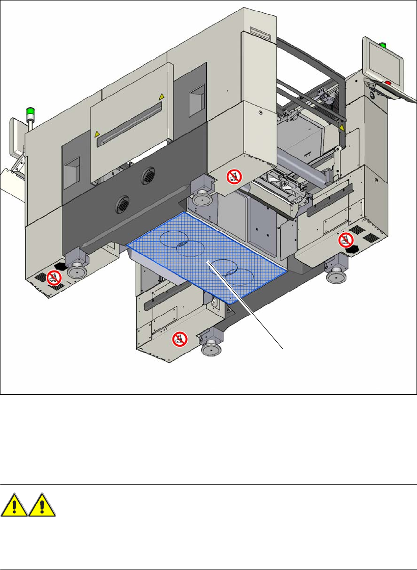
Fig. 4.1 - 4 Contact surfaces - forks parallel to the direction of PCB transport (example of SX1/SX2)
(1) Contact surface for fork lift truck forks
4.1.5.4 Points that MUST be noted when transporting the machine
WARNING 4
When you are transporting the machine, make sure that all the feet are clear of the floor. If they
are not clear, the feet will drag along the floor or bump into obstacles. This could damage the
machine feet and/or the foot fixtures.
(1)

User Manual SIPLACE SX1/SX2/DX1/DX2 4 Setting up and commissioning
From software version SC.706.xx Version 06/2012 EN 4.2 Infrastructure at the installation location
209
4.2 Infrastructure at the installation location
4.2.1 Recommendations for the foundation quality
The foundation on which the machine is installed must be firm and level, as dynamic forces could
cause vibrations when the machine is operated. The degree of vibration depends on the construc-
tion of the foundation. The following are suitable provided that the floor loading parameters, etc.,
are not exceeded:
– Reinforced concrete ceiling constructions, e.g. ceilings in production halls
– Reinforced concrete floor slabs, e.g. concrete floors in production halls without a basement
– Rooms with double floors, provided that a stable foundation is included in the space between
them. The same setup conditions apply to this intermediate foundation, which can be made
from steel girders or concrete.
4.2.1.1 Maximum ground levelness
The floor underneath the machine may not exceed an incline of 0.63%. This corresponds to an
incline of 5 mm over a distance of 800 mm (e.g. the width of a changeover table).
4.2.1.2 Machine weight and floor loading
the machine weight and floor loading values can be found in section 3.4.1, page 107.
4
4.2.2 Compressed air supply
4.2.2.1 Checking the compressed air supply
Check whether the compressed air supply complies with the prescribed machine specifications
(see table in section 3.3
, page 105).
PLEASE NOTE: 4
The documentation "Network Configuration (Electrics and Compressed Air) for SMD Machines at
Customer Site", Item No. 00191409-xx includes the measures required to achieve the specifica-
tions needed.
Record the compressed air characteristics at the installation location.
WARNING
NEVER detach compressed air lines while they are still pressurized. Risk of injury. 4
4 Setting up and commissioning User Manual SIPLACE SX1/SX2/DX1/DX2
4.2 Infrastructure at the installation location From software version SC.706.xx Version 06/2012 EN
210
4.2.2.2 Compressed air connection on the machine
4
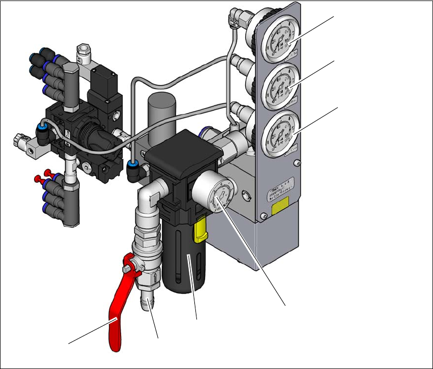
Fig. 4.2 - 1 Compressed air unit on the machine
Legend for fig.4.2 - 1
(1) Manometer for supply pressure of gantries 1 and 2
Target pressure: 0.46 ± 0.01 MPa, 4.6 ± 0.1 bar (display range 0 - 0.6 MPa, 0 - 6 bar)
(2) Manometer for the machine component supply pressure
Target pressure: 0.5 ± 0.025 MPa, 5 ± 0.25 bar (display range 0 - 0.6 MPa, 0 - 6 bar)
(3) Manometer for the bulkcase feeder module supply pressure
Target pressure: 0.25 ± 0.05 MPa, 2.5 ± 0.5 bar (display range: 0 - 0.6 MPa, 0 - 6 bar)
(4) Manometer for inlet pressure
Target pressure: 0.5 - 1.0 MPa, 5 - 10 bar (display range: 0 - 1.0 MPa, 0 - 10 bar)
(5) Compressed air filter
(6) Compressed air connection
(7) Stop valve in the "OPEN" position
(6)
(1)
(2)
(3)
(4)
(5)
(7)