00196457-05_UM_SX12DX12_SR706_EN.pdf - 第81页
User Manual SIPLACE SX1/SX2/DX1/DX2 2 Operational safety From software version SC.706.xx Version 06/2012 EN 2.8 Re sidual voltages and discharge times in the machine 81 Fig. 2.8 - 2 Measuring point s on the power supply …
2 Operational safety User Manual SIPLACE SX1/SX2/DX1/DX2
2.8 Residual voltages and discharge times in the machine From software version SC.706.xx Version 06/2012 EN
80
2.8 Residual voltages and discharge times in the machine
If the EMERGENCY STOP button is pressed or the machine is switched off, the 260 VDC link volt-
age for the gantry axes and the 150 VDC link voltage for the star axes are reduced to harmless
residual voltages in a very short time.
WARNING 2
The machine is supplied with 3 x 200 V~, 3 x 208 V~, 3 x 220 V~, 3 x 230 V~, 3 x 380 V~,
3x400V~ or 3x415V~ ± 5%, 50/60Hz mains voltage. This means that some parts of the sys-
tem carry potentially lethal voltages - even when switched off at the main power switch. Incorrect
handling of the machine can therefore result in death or severe injury or considerable damage to
equipment.
Always follow the applicable accident prevention and DIN regulations (particularly EN 60204,
part 1 or IEC 60204, part 1) and the applicable regulations in your own country.
The covers over the power supply unit may ONLY be opened by appropriately qualified and
trained personnel.
2
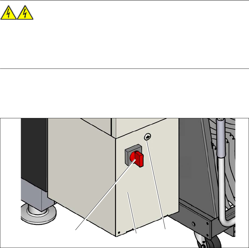
Fig. 2.8 - 1 Power supply unit (example of SX1/SX2)
(1) Main power switch
(2) Power supply unit behind the cover
(3) Padlock with bolt in the cover
(3)
(1)
(2)
User Manual SIPLACE SX1/SX2/DX1/DX2 2 Operational safety
From software version SC.706.xx Version 06/2012 EN 2.8 Residual voltages and discharge times in the machine
81
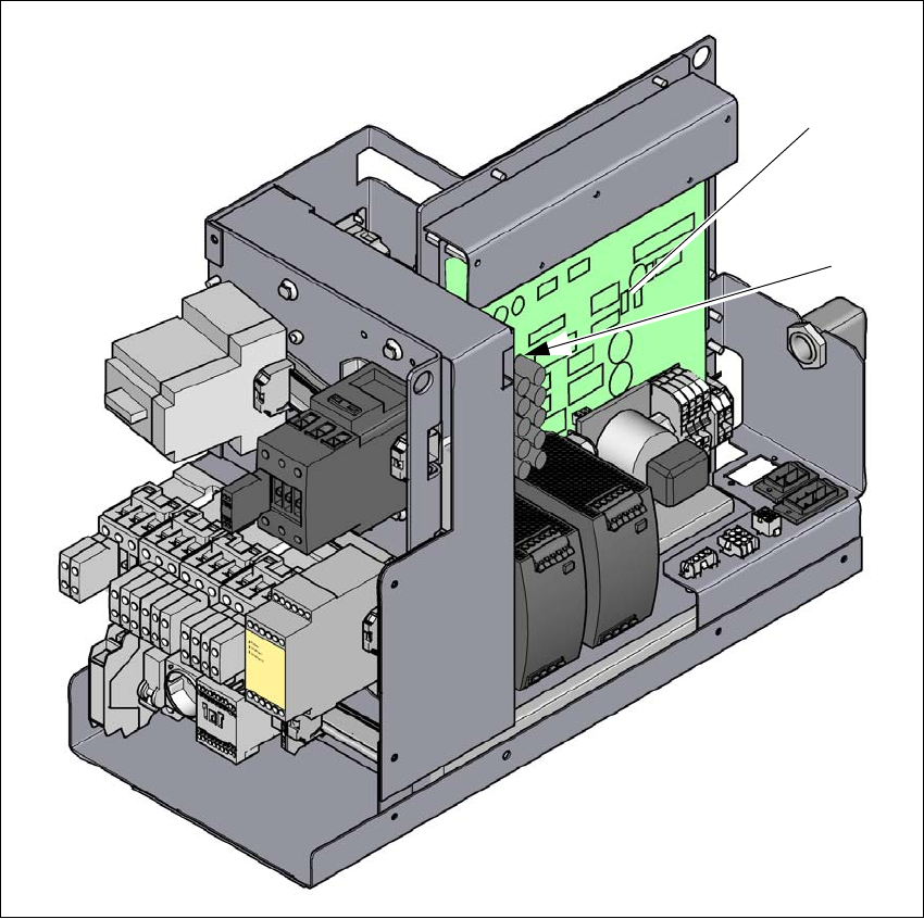
Fig. 2.8 - 2 Measuring points on the power supply unit
(1) Fuse and distributor board (A3)
(2) Rectifier board (A7)
(1)
(2)

2 Operational safety User Manual SIPLACE SX1/SX2/DX1/DX2
2.8 Residual voltages and discharge times in the machine From software version SC.706.xx Version 06/2012 EN
82
2.8.1 Residual voltages and discharge times after switching off the main switch
2
2.8.2 Residual voltages and discharge times after pressing the EMERGENCY
STOP button
2
Measurement point on the
fuse and distributor board
(A3)
(terminal/pin)
Voltage in
normal mode
Residual voltage if
main switch OFF or
power failure
Discharge
times
XB8a / XB8b; Pin 1 in each case 150 V- < 10 VDC < 2s
X25, Pin 1 42 V- < 10 VDC < 2s
X1A / X1B, Pin1 in each case 24 V- < 10 VDC < 2s
XB4; Pin 6 24 V- < 10 VDC < 2s
Measurement point on the
rectifier board (A7
(terminal/pin)
Voltage in
normal mode
Residual voltage if
main switch OFF or
power failure
Discharge
times
XB7a/XB7b, Pin1 in each case 260 V- < 10 VDC < 2s
At the marked point on the rec-
tifier DC40V-S 42 V- < 10 VDC < 2s
Measurement point on the
fuse and distributor board
(A3)
(terminal/pin)
Voltage in
normal mode
Residual voltage after
EMERGENCY STOP
Discharge
times
XB8a / XB8b; Pin 1 in each case 150 V- < 10 VDC < 2s
XB4; Pin 6 24 V- < 10 VDC < 2s
Measurement point on the
rectifier board (A7
(terminal/pin)
Voltage in
normal mode
Residual voltage after
EMERGENCY STOP
Discharge
times
XB7a/XB7b, Pin1 in each case 260 V- < 10 VDC < 2s
At the marked point on the rec-
tifier DC40V-S 42 V- < 10 VDC < 2s