00196457-05_UM_SX12DX12_SR706_EN.pdf - 第147页
User Manual SIPLACE SX1/SX2/DX1/DX2 3 Technical data and assemblies From software version SC.706.xx V ersion 06/2012 EN 3.8 PCB conveyor system 147 3.8.3 Structure of the fl exible PCB dual conveyor The flexible dual con…
3 Technical data and assemblies User Manual SIPLACE SX1/SX2/DX1/DX2
3.8 PCB conveyor system From software version SC.706.xx Version 06/2012 EN
146
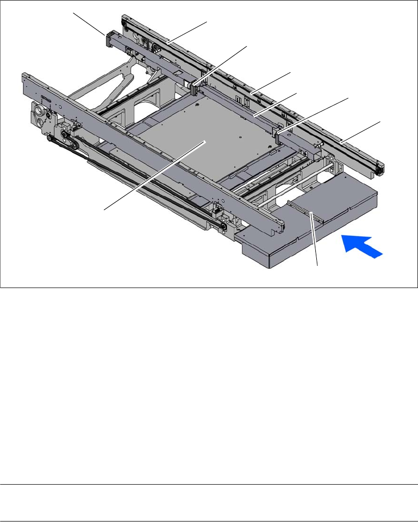
3.8.2 Design of the PCB single conveyor
3
Fig. 3.8 - 1 Design of the PCB single conveyor
(1) Input conveyor
(2) Stopper - input area
(3) Stop bar
(4) Processing conveyor
(5) Stopper - processing area
(6) Output conveyor
(7) Stopper - output area
(8) Lifting table
(9) Conveyor control (under the cover)
NOTE
The free positioning of board supports is limited by the stop bar. 3
(5)
(1)
(3)
(7)
(8)
(6)
(4)
(2)
(9)
User Manual SIPLACE SX1/SX2/DX1/DX2 3 Technical data and assemblies
From software version SC.706.xx Version 06/2012 EN 3.8 PCB conveyor system
147
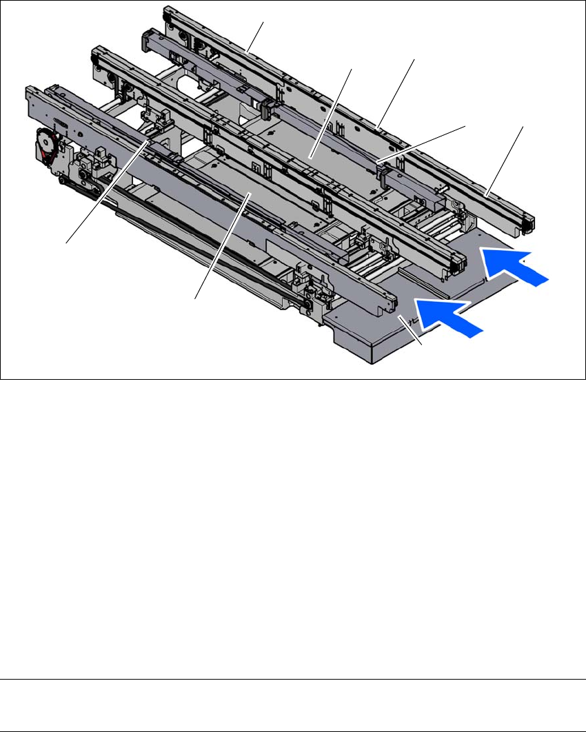
3.8.3 Structure of the flexible PCB dual conveyor
The flexible dual conveyor has two conveyor tracks that are electrically and mechanically inde-
pendent of one another. The fixed conveyor side is on the right as a standard. The PCB dual con-
veyor can be operated as a single or dual conveyor, according to your needs.
3
Fig. 3.8 - 2 Structure of the PCB dual conveyor
(1) Input conveyor
(2) Stop bar - conveyor lane 1
(3) Processing conveyor
(4) Lifting table 1
(5) Output conveyor
(6) Stop bar - conveyor lane 2
(7) Lifting table 2
(8) Conveyor control (under the cover)
T1 Conveyor track 1
T2 Conveyor track 2
NOTE
The free positioning of board supports is limited by the stop bars. 3
(5)
(1)
(3)
(4)
(7)
(8)
(T1)
(T2)
(2)
(6)
3 Technical data and assemblies User Manual SIPLACE SX1/SX2/DX1/DX2
3.8 PCB conveyor system From software version SC.706.xx Version 06/2012 EN
148
3.8.3.1 Flexible PCB dual conveyor - conveyor lanes and types
The right-hand conveyor lane (viewed in the direction of transport) is known as "conveyor 1" while
the left conveyor lane is termed "conveyor 2" (see fig. 3.8 - 4
, page 149 ).
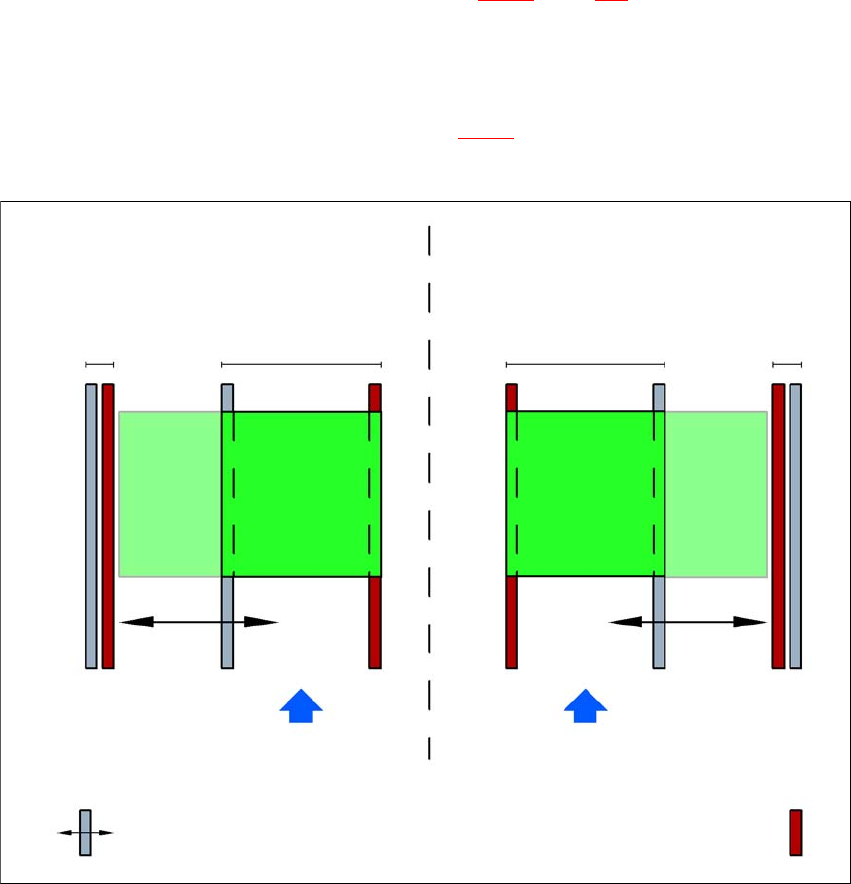
3.8.3.2 PCB dual conveyor in single conveyor mode
The dual conveyor can be configured online to create a single conveyor. One conveyor lane is
moved together completely and is disabled (see fig. 3.8 - 3
). This gives a conveyor track width of
up to 460 mm.
3
Fig. 3.8 - 3 Flexible dual conveyor in Single conveyor mode
Dual conveyor with widened conveyor track 2
(stationary conveyor side wall on left)
Conveyor track 2
deactivated
Conveyor track 1 Conveyor track 2 Conveyor track 1
deactivated
PCB transport direction PCB transport direction
Stationary conveyor side wall
Dual conveyor with widened conveyor track 1
(stationary conveyor side wall on right)
Movable conveyor side wall