00196457-05_UM_SX12DX12_SR706_EN.pdf - 第198页
3 Technical data and assemblies Us er Manual SIPLACE SX1/SX2/DX1/DX2 3.11 Component trolley for SIPLACE SX1/SX2 From software version SC.706.xx Version 06/2012 EN 198 3.1 1.10 Empty t ape duct on th e component trolley d…
User Manual SIPLACE SX1/SX2/DX1/DX2 3 Technical data and assemblies
From software version SC.706.xx Version 06/2012 EN 3.11 Component trolley for SIPLACE SX1/SX2
197
3.11.8.2 Maximum tape reel diameter in relation to the PCB conveyor height
3
PLEASE NOTE: 3
SIPLACE SX1/SX2 component trolleys do not generally need spindles. However, if the "Timeout"
error message occurs increasingly on the X feeder module, we recommend that you do use spin-
dles.
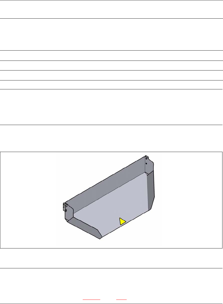
3.11.9 Used tape chute
3
Fig. 3.11 - 10 Used tape chute for the component trolley docking unit
PLEASE NOTE 3
The used tape chute for the SIPLACE SX1/SX2 can only be installed on the component trolley
docking unit
for the SIPLACE SX1/SX2 (see fig. 5.15 - 4, page 300).
Without mount for the
additional tape reel
With mount for the
additional tape reel
PCB conveyor
height
of the component
trolley
Tape reel diameter Tape reel diameter
without spindle with spindle
900 mm 19" 17" 15"
930 mm 19" 19" 17"
950 mm 19" 19" 19"
3 Technical data and assemblies User Manual SIPLACE SX1/SX2/DX1/DX2
3.11 Component trolley for SIPLACE SX1/SX2 From software version SC.706.xx Version 06/2012 EN
198
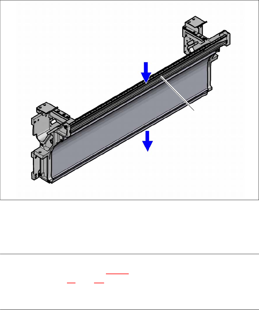
3.11.10 Empty tape duct on the component trolley docking unit
In the standard version, the empty tape duct can guide component tapes with a maximum pocket
height of 12 mm to the pneumatic tape cutter.
3
Fig. 3.11 - 11 Empty tape duct on the SIPLACE SX1/SX2 component trolley docking unit
(1) Inlet slot for the used tapes
(2) Outlet slot for the used tape above the pneumatic tape cutter
(3) Dividing plate for tapes < 12 mm (can be removed for tapes > 12 mm)
PLEASE NOTE
– The separating plate (item 3 in fig. 3.11 - 11
) can be removed for tape pockets higher than
12 mm (see section 4.5
, page 238).
Do not position feeder modules with shallow pockets immediately beside feeder modules with
deep pockets. The used tapes could overlap and build up.
(1)
(2)
(3)
User Manual SIPLACE SX1/SX2/DX1/DX2 3 Technical data and assemblies
From software version SC.706.xx Version 06/2012 EN 3.12 DX table on the SIPLACE DX1/DX2
199
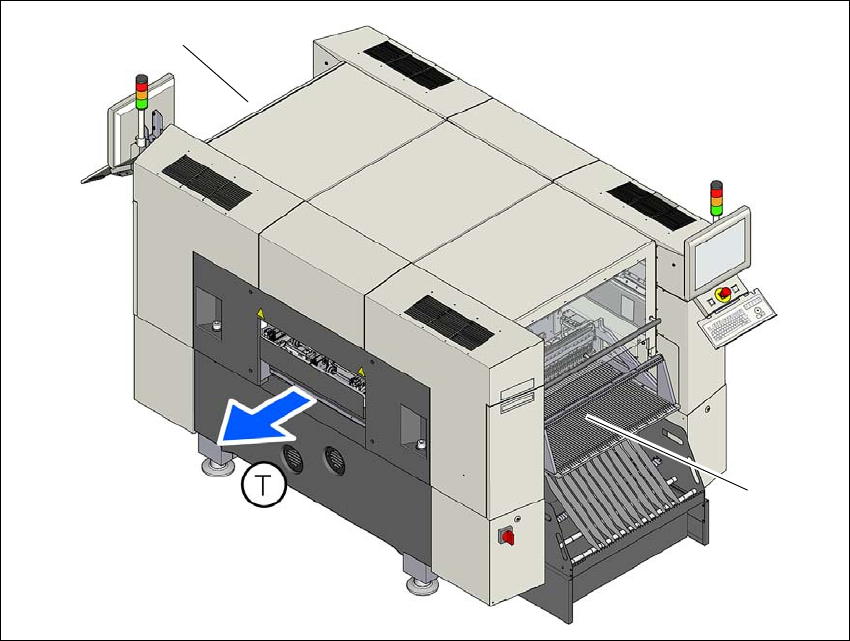
3.12 DX table on the SIPLACE DX1/DX2
In its default configuration, the SIPLACE DX1/DX2 has two DX tables which, if used with 30 SI-
PLACE 2x8mm X feeder modules, can be set up to achieve capacity of up to 60 tracks for accom-
modating component types.
Feeder module handling on these DX tables is basically the same as that on the changeover ta-
bles used with the SIPLACE SX1/SX2.
3
Fig. 3.12 - 1 DX table locations, SIPLACE DX1/DX2
(1) Location 1
(2) Location 2
(T) Direction of PCB transport
(1)
(2)