CP45-英文版培训教材.pdf - 第118页
Operating Manual Reference Figure CP-45/55 Operation Process Also, this can be used when an user want to assign specially the head to work for a certain nozzle. A figure above shows that TN14 nozzle can be worked at any …

Operating Manual Reference Figure
CP-45/55 Operation Process
^ <Nozzle> Area/ <Nozzle #1 #2>
List Box
This List Box shows all nozzles
being used on PCB under edit,
and also displays the status
indicated with the 1st and the
2nd work nozzles of part for
individual nozzle.
#1and#2representthe1st
work nozzle and the sums of
the place origins of part
assigned with the 2nd work
nozzle respectively.
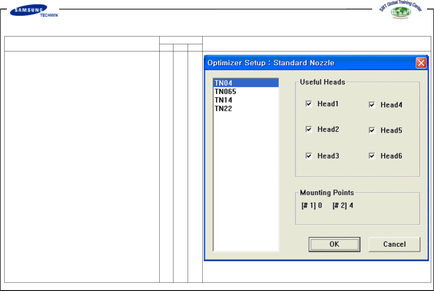
^ <Assign Nozzle> Button
This can be used for assigning
the head applicable to individual
nozzle. If pressing this button,
a Dialogue Box will be shown as
follows. Because all nozzle types
can be worked at any head
basically, that nozzle types were
checked in all heads. However,
in some cases, a certain nozzle
should be worked on a certain
head.
Operating Manual Reference Figure
CP-45/55 Operation Process
Also, this can be used when an
user want to assign specially the
head to work for a certain nozzle.
A figure above shows that TN14
nozzle can be worked at any
head from Head1 to Head6.
^ <Useful Heads> Check Box Area
This refers to Useful Heads
for the nozzle type selected.
Check Head1, Head2, Head3,
Head4, Head5 and Head6 as the
basic value.
^ <Mounting Points> Area
This area shows the numbers of
part used by the nozzle selected
on the current PCB. This can
be used as the data for reference
when an user assigns the head
applicable to individual nozzle.
#1 represents the numbers of
total mounting points of part
selected by No.1 nozzle, and #2
represents the numbers of total
mounting points selected by
No. 2 nozzle.
Operating Manual Reference Figure
CP-45/55 Operation Process
^ <OK> Button
This saves the option selected
above and closes the Dialogue
Box.
^ <Cancel> Button
This cancels the option selected
above and closes the Dialogue
Box.
This screen is to set the
individual Feeder Lane to be used
for Feeder Arrangement on
Optimizer. Units possible to arrange
on Feeder Lane are Tape Feeder,
Stick Feeder Unit, Moving ANC,
Feeder Lane Fixed Camera Unit,
etc. On this screen you can assign
the Feeder Lane prohibiting unit
from arrangement on the Optimizer.
^ <Arranged> List Box
This shows the status of
Feeder Lane and Tape Feed
placed already, Moving ANC,
Camera, etc.
* Setup Menu/Feeder Lane