CP45-英文版培训教材.pdf - 第77页
Operating Manual MODEL Reference Figure CP-45/55 Operation Process V BGA Register Click the <New Part… > button on the left of the bottom of a screen. Create the Part Name.(BGA256) Select the Group to BGA. Enter th…
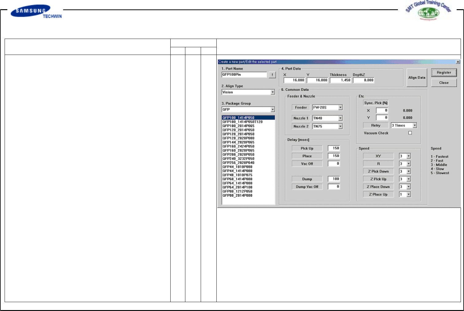
Operating Manual
MODEL
Reference Figure
CP-45/55 Operation Process
Enter the Common Data by
pressing the <Common Data>
button.
Select FW-20S on <Feeder>
Combo Box.
Select TN40 and TN75 on
<Nozzle 1> and <Nozzle 2>
Combo Box separately.
Register the part by clicking
the <Register> button.
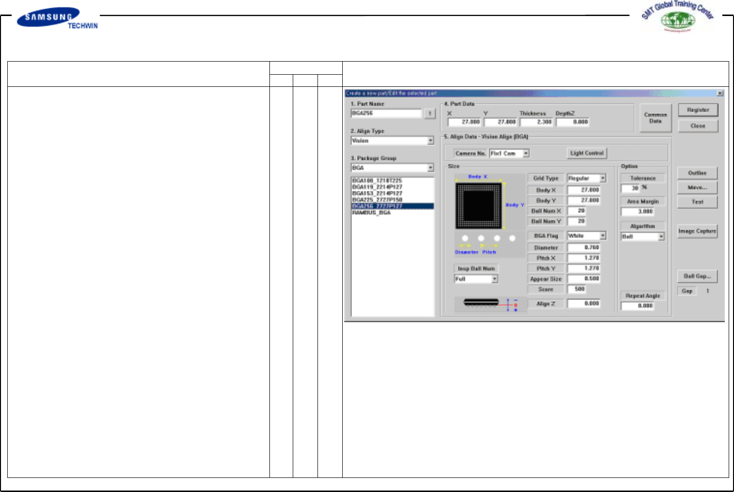
Operating Manual
MODEL
Reference Figure
CP-45/55 Operation Process
V
BGA Register
Click the <New Part…> button on
the left of the bottom of a
screen.
Create the Part Name.(BGA256)
Select the Group to BGA.
Enter the Part Size.
# Grid Type:
Selection among <Regular, Check,
Rev.check>
# Body Size:
Enter the Body Size.
(BodyX,Y,Thickness)
# Ball Quantity: Enter the Ball
quantity of X and Y columns.
# BGA Flag: Select a color of Ball.
(Commonly select White.)
#Diameter:
Enter the diameter of Ball.
#Pitch:
Enter the distance between Balls.
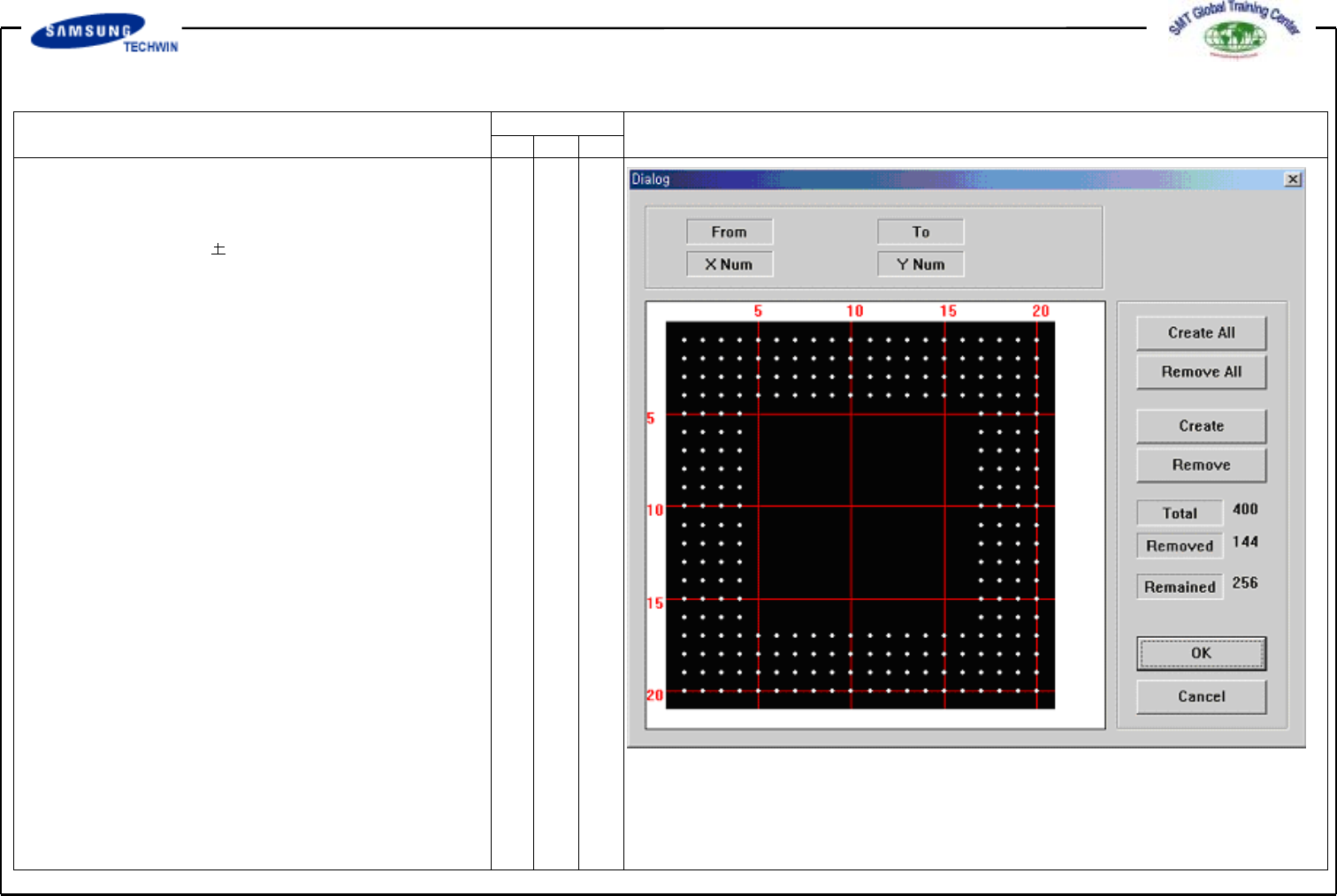
Operating Manual
MODEL
Reference Figure
CP-45/55 Operation Process
"Ball Gap of BGA Part-Initial Status” Dialogue Box
# Appear Size:
Enter the allowable range of Ball
Size.
Ball Size appear size= Actual
Size
# Score: Acceptance score of Ball,
i.g. shape reflection degree of
Ball.
# Ball Gap: If there is empty Ball
in Ball Array, select the empty
Ball.
This is activated only when
<Grid Type> is “Regular”.
If clicking this button, a Message
Box as shown in the right will be
shown.
The grid represents the current
status of the Ball. White color
represents the Ball. If you want
to remove the Ball on a certain
range, firstly define the area to
select. To select the range, press
the left button of a mouse, drag
the range and release the mouse
button. Color of the Ball selected
will be changed. Next, display a
screen selected Ball of total 25
ranging5toXdirectionand5to
Y direction from (4, 4) Ball to
(10, 10) Ball.