CP45-英文版培训教材.pdf - 第180页
Operating Manual Reference Figure CP-45/55 Operation Process 1.2.5 Feeder Station Parts 1.2.5.1 Feeder Base *Check Points* @Check that small debris or foreign materials are adhered to the surface of the base prior to fix…
Operating Manual Reference Figure
CP-45/55 Operation Process
1.2.4 Electric Device
*Check Points*
@Check every device for worn
conditions.
@Check that an error occurs to the
system during Switch operations.
@Check that the relevant input IO of
MMI IO window operates properly.
(Emergency Switch , Door Switch)
@Check whether the power is off or
not during the current breaker
operations.
*Actions to be taken*
@If the part is worn excessively or
fails to operate, contact our
designated C/S company for A/S.
Caution
Be sure to turn off and lock the power when
checking for the wear conditions.
Operating Manual Reference Figure
CP-45/55 Operation Process
1.2.5 Feeder Station Parts
1.2.5.1 Feeder Base
*Check Points*
@Check that small debris or foreign
materials are adhered to the surface
of the base prior to fixing the
feeder.
@Check the fixing slot for abnormal
wear.
Caution
If the foreign materials are adhered to the surface of
the feeder, the functional problems may occur when
mounting the part actually. Clean out the foreign
materials and then mount the part.
Abnormal wear may have an effect on the reliability
of part pickup. Contact our designated C/S company
for taking corrective actions.
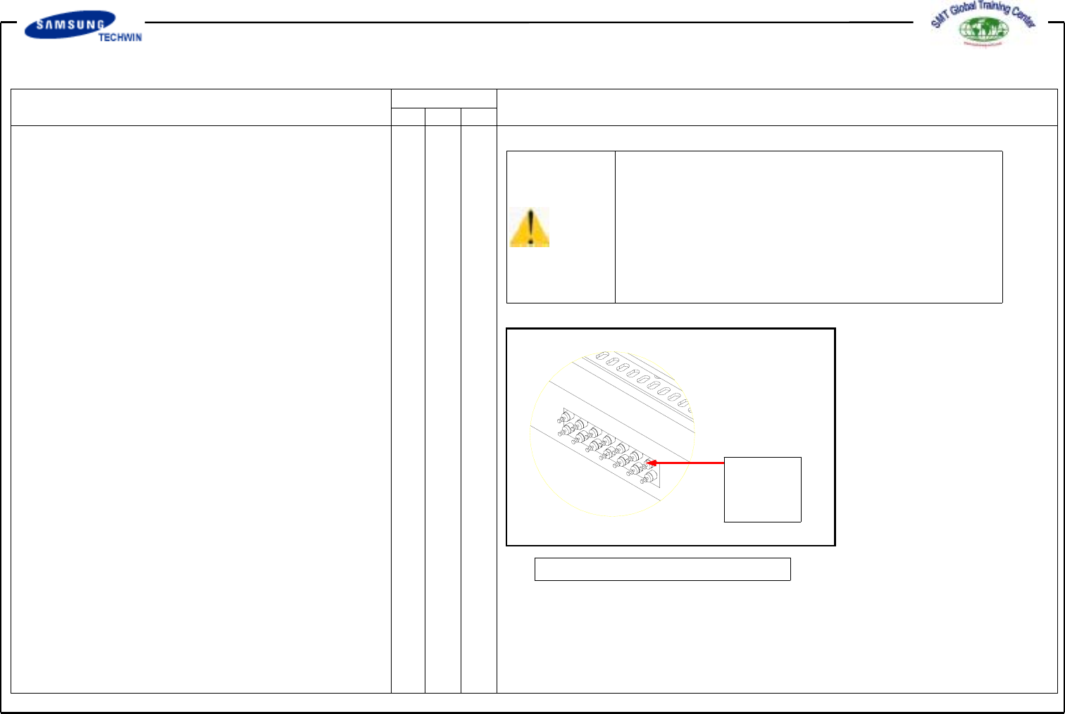
1.2.5.2 Multi Cylinder Speed Control
*Check Points*
@Check that some problems occur
to part mounting caused by the
shock speed of a cylinder which
drives the part feeder.
*Actions to be taken*
@Control the speed with the speed
control valve of the multi cylinder.
Speed
Control
Valve
Fig. 117. Speed Control Valve
Operating Manual Reference Figure
CP-45/55 Operation Process
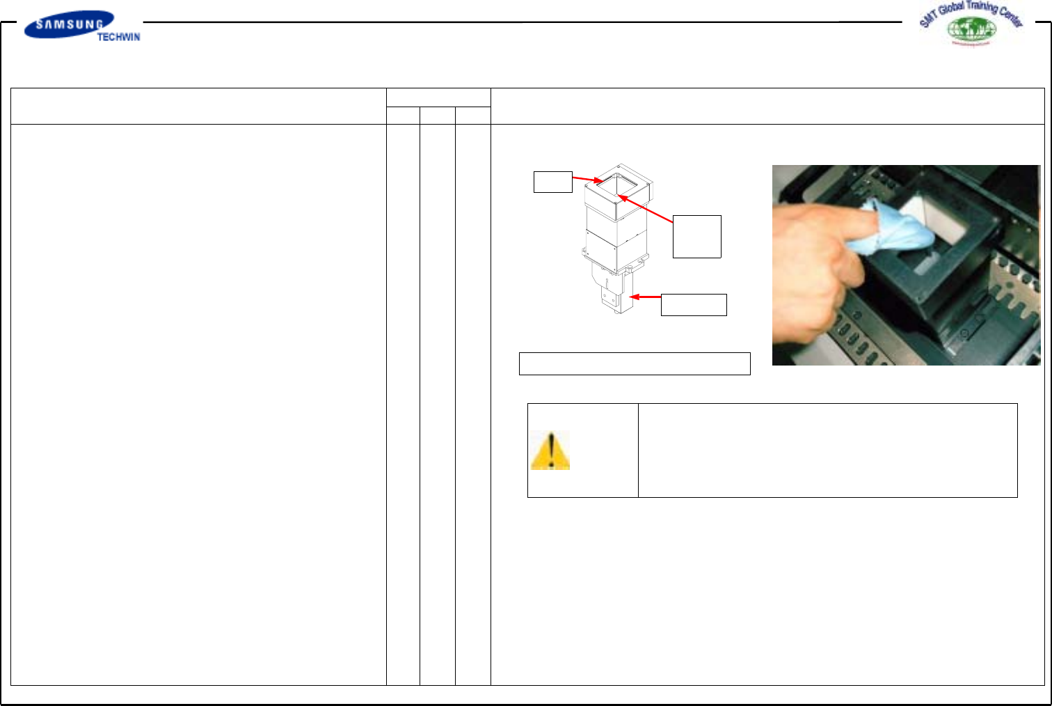
1.2.6 Upward Vision
1.2.6.1 Cover Glass
*Check Points*
@Check that dust particles, foreign
materials, etc., are adhered to both
sides of Cover Glass
*Actions to be taken*
@Loosen 4 screws at both sides of
LED assembly to disconnect it.
@Clean out both sides of Cover Glass
with soft cloth.
@Assemble the part in the reverse
order.
LED
Cover
Glass
Camera
Fig. 118.Upward Vision
Caution
Cover Glass is easy to break since its material is
glass. Care is to be taken for prohibiting from that.
1.2.6.2 Camera Lens
*Actions to be taken*
@Loosen 4 screws at both sides of
LED assembly to disconnect it.
@Clean out the camera Lens with
soft cloth.
@Assemble the part in the reverse
order.
*Check Points*
@Check that dust particles, foreign
materials, etc. are adhered to the
Camera Lens.