CP45-英文版培训教材.pdf - 第193页
Operating Manual Reference Figure CP-45/55 Operation Process 3. Difference between The Existing Feeder and Non Stop Tape Feeder 3.1 Development Drawing Drain-type Tape Feeder Non Stop Tape Feeder
Operating Manual Reference Figure
CP-45/55 Operation Process
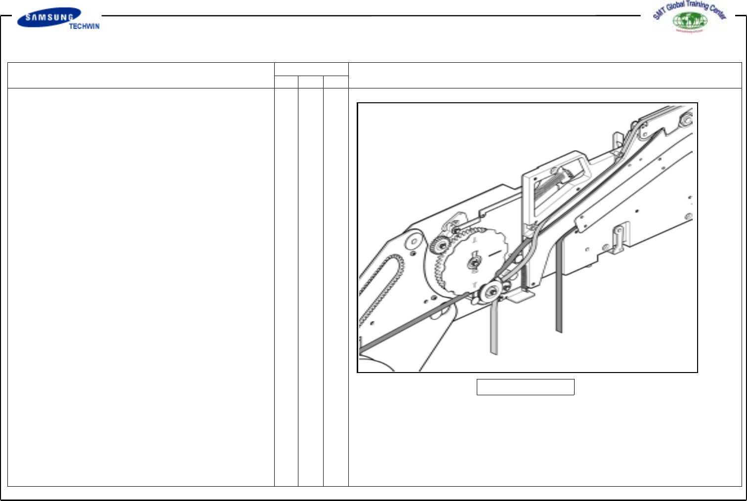
2.2.3 Non Stop Tape Feeder
[Fig.2.2.2]
-> Fixing method of 8mm Non-Stop
tape feeder depends upon the
types such as drain type, take up
type, etc.
For drain type, put the upper cover
tape between idler gear and
forminggearbyhangitonRoller
A and B, passing it through the
slot B and placing it under
Roller D and above the Roller E.
At this time, Fix the upper cover
tape by pulling it tightly and
putting between two gears above.
Also care is to be taken for
ensuring that the upper cover tape
can be passed through evenly
without being folded or skipping
over rollers or gears when passing
through roller E or idler gear and
forming gear.
For take up type, apply the same
method as fixing method of the
existing take up tape feeder upper
cover tape. Refer to [Fig. 2.2.1].
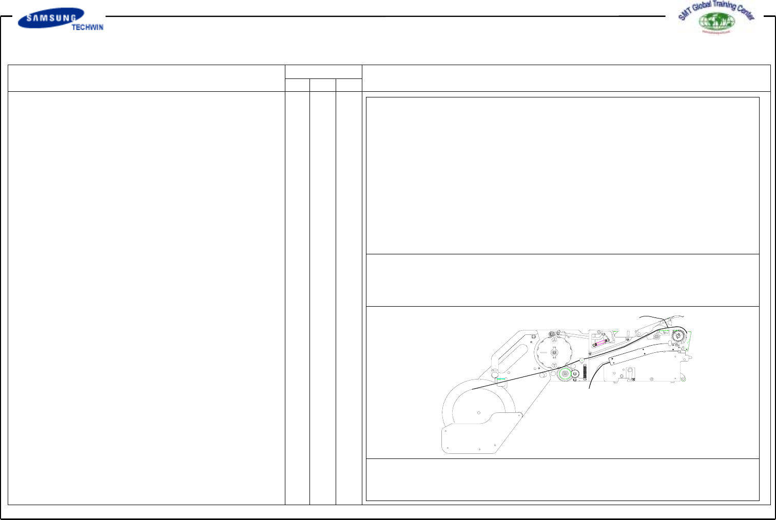
Operating Manual Reference Figure
CP-45/55 Operation Process
3.
Difference between The Existing
Feeder and Non Stop Tape
Feeder
3.1 Development Drawing
Drain-type Tape Feeder
Non Stop Tape Feeder
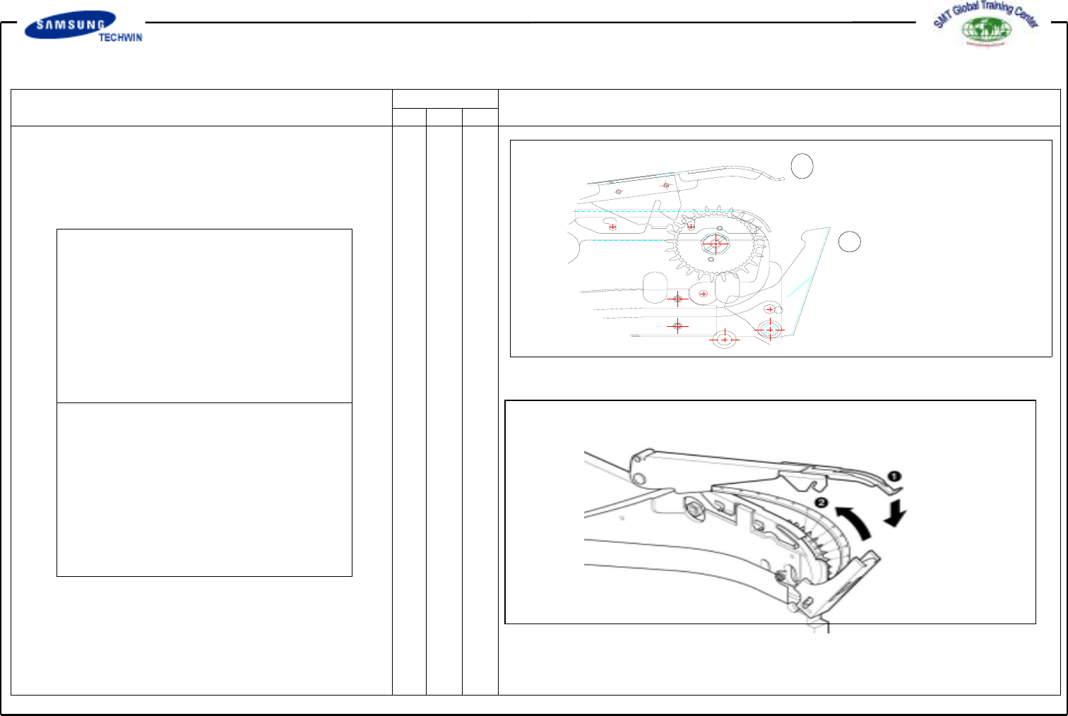
Operating Manual Reference Figure
CP-45/55 Operation Process
3.2 Difference Analysis
3.2.1 Difference of Tape Guide Fixing
Part
Problems : Locker is easy to open
even responding to micro
shock as a result of poor
locking caused by a shock of
a head and a feeder of the
chip mounter.
Problem of shock with Head was
improved.
It is judged that the locker will
not open during operation if once
locked.
1
2
Method of inserting No.1 tape guide into slot of No.2 locker
Method of clamping ends of No.1 tape guide with ends of No.2 locker