CP45-英文版培训教材.pdf - 第179页
Operating Manual Reference Figure CP-45/55 Operation Process 1.2.4 Electric Device *Check Points* @Check every device for worn conditions. @Check that an error occurs to the system during Switch operations. @Check that t…

Operating Manual Reference Figure
CP-45/55 Operation Process
1.2.3.9 Operation of Conveyor
Cylinder
*Check Points*
@Check individual cylinder for proper
operation.
@Check for the operation sensor of
individual cylinder.
*Actions to be taken*
@You may use Manual I/O Test, Self
Diagnostic on MMI monitor for
easy check.
@If abnormal conditions occur,
contact our C/S center for A/S.
Caution
Avoid inserting parts of a body into the system during
I/O Test. Failing to observe this may cause serous
injury to personnel.
Operating Manual Reference Figure
CP-45/55 Operation Process
1.2.4 Electric Device
*Check Points*
@Check every device for worn
conditions.
@Check that an error occurs to the
system during Switch operations.
@Check that the relevant input IO of
MMI IO window operates properly.
(Emergency Switch , Door Switch)
@Check whether the power is off or
not during the current breaker
operations.
*Actions to be taken*
@If the part is worn excessively or
fails to operate, contact our
designated C/S company for A/S.
Caution
Be sure to turn off and lock the power when
checking for the wear conditions.
Operating Manual Reference Figure
CP-45/55 Operation Process
1.2.5 Feeder Station Parts
1.2.5.1 Feeder Base
*Check Points*
@Check that small debris or foreign
materials are adhered to the surface
of the base prior to fixing the
feeder.
@Check the fixing slot for abnormal
wear.
Caution
If the foreign materials are adhered to the surface of
the feeder, the functional problems may occur when
mounting the part actually. Clean out the foreign
materials and then mount the part.
Abnormal wear may have an effect on the reliability
of part pickup. Contact our designated C/S company
for taking corrective actions.
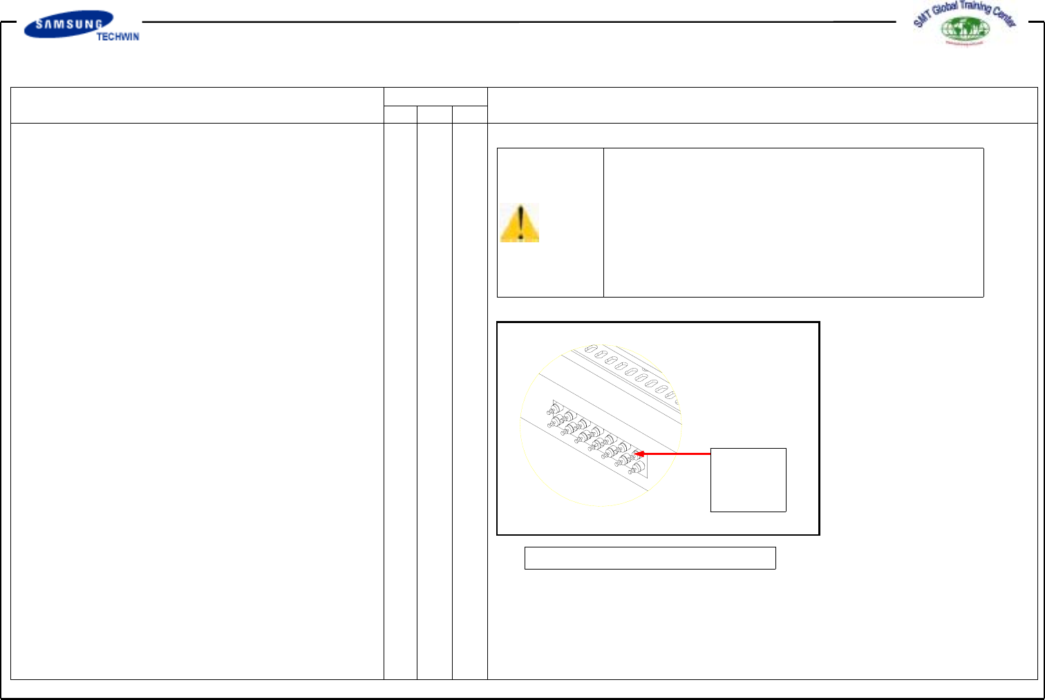
1.2.5.2 Multi Cylinder Speed Control
*Check Points*
@Check that some problems occur
to part mounting caused by the
shock speed of a cylinder which
drives the part feeder.
*Actions to be taken*
@Control the speed with the speed
control valve of the multi cylinder.
Speed
Control
Valve
Fig. 117. Speed Control Valve