CP45-英文版培训教材.pdf - 第161页
Operating Manual Reference Figure CP-45/55 Operation Process 1.2.1 Head Part 1.2.1.1 Flying Vision * Check Points * If foreign materials are adher ed to the upper surf ace of a mirror , the shap e acknowledgement of visi…
1.2 Repair, Inspection and Maintenance of Individual Part
Warning
Failing to turn off the power switch may cause serious injury to personnel. Be
sure to turn off the power switch when maintaining individual part. Moving the
gantry by pushing the head manually may cause severe damage to the system or
injury to personnel resulted from mis-operation of the system. Do not operate the
gantry manually.
Operating Manual Reference Figure
CP-45/55 Operation Process
1.2.1 Head Part
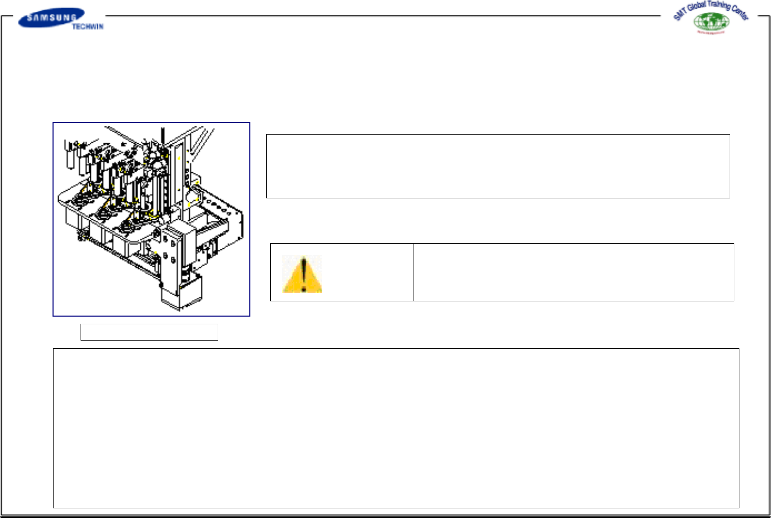
1.2.1.1 Flying Vision
* Check Points *
If foreign materials are adhered to the upper surface of a mirror, the shape
acknowledgement of vision can not be achieved properly. Thus, check that there are dust
particles or foreign materials on the upper surface of a mirror on occasion.
Clean out lens with Cleaning Kit supplied with the
system.
Caution
* Actions to be taken *
@Stop the operating system and move the Head Ass'y forward as possible.
@Rise the Mirror up.
@Turn off the power of a system. Turn off the power, if required, and pull the X-Frame to move forward.
@Blow off dust particles on lens with an air blast included in the Cleaning Kit supplied by this company.
@Clean out the dust particles adhered to the clearance of approx. 1cm between the Light Ass'y Bracket and Lens
viewed from the lower with cotton buds. If necessary, clean out the Lens with cotton buds with a small quantity of
alcohol.
@If cleaned out by use of alcohol, carefully clean out the surface of lens with a clean cotton bud one more time
finally.
Fig 1-1.Flying vision
Operating Manual Reference Figure
CP-45/55 Operation Process
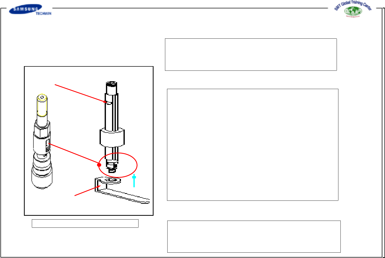
A
B
1.2.1.2 Compliance Assembly
* Check Points *
Compliance can be bent caused by improper operation during the
part mounting. Thus, be sure to check the spring
force and bending condition of the compliance occasionally.
*When disassembling the Compliance Assembly from
the Head
(1) Hold the spline upper slot(A) of Head with a
spanner.
(2) Insert the fixture(B) for assembling the compliance
into the compliance assembly to the arrow direction.
(3) Loosen the fixture for assembling the compliance
until the compliance assembly can be loosened
by hands.
(4) Loosen and remove the compliance assembly by hands.
*When assembling the Compliance Assembly to the Head
Tighten the compliance assembly in reverse order for
disassembly. Fix the compliance assembly by installing the
fixture(B) for assembling the Compliance.
*Actions to be taken*
Disconnect the damaged compliance from the spindle
with a 8mm wrench, and then install the new compliance
in reverse order for disassembly.
FIG. 1-2 Compliance Assembly