CP45-英文版培训教材.pdf - 第201页
Operating Manual Reference Figure CP-45/55 Operation Process 4.2 Inspection and Adjustment Method Step1 : Inspection Jig Origin Point Setting 1 If fixing the master jig to the inspection jig, the left edge of a block on …
Operating Manual Reference Figure
CP-45/55 Operation Process
4.1.3 Installation Guide of Product
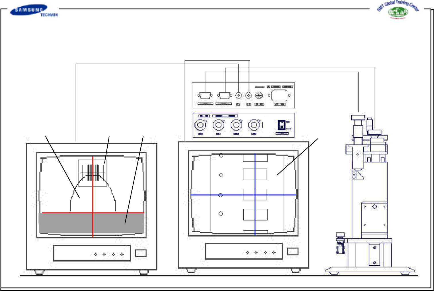
Transparent FilmSprocket
Tape Guide
Monitor 1 <-> M1
Monitor 2 <-> M2
Camera 2 <-> Pocket Inspection
Camera 1 <->Sprocket Inspection
Tape Reel
Operating Manual Reference Figure
CP-45/55 Operation Process
4.2 Inspection and Adjustment Method
Step1 : Inspection Jig Origin Point Setting 1
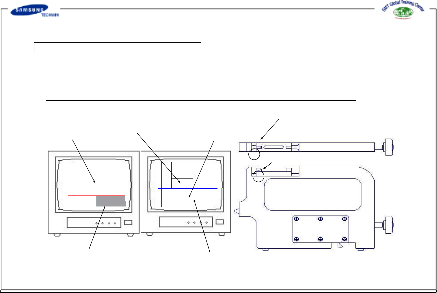
If fixing the master jig to the inspection jig, the left edge of a block on the top of the master jig will be shown on the
monitor 1, and the top of the master jig block will be shown on the monitor 2.
If the monitor can not be in complete focus, adjust the focus by turning the camera focus adjusting screw fixed on the
inspection jig.
* (Caution) - If re-adjusting the focus after adjusting it once, variance may be occurred to the position.
Gear Center Line
4mm Pitch Pocket Reference Line
2mm Pitch Pocket Reference Line
Tape Guide Reference Line
Pocket Center Line
[Monitor1
(for gear inspection) ]
[Monitor2(forpocket
inspection) ]
[ Master Jig ]
Area where will be shown on Monitor 2
Area where will be shown on Monitor 1
Operating Manual Reference Figure
CP-45/55 Operation Process
Step2 : Inspection Jig Origin Point Setting 2
If a position was shown on the monitor, align the vertical line and the horizontal line which was shown on
the monitor 1 by adjusting the H1 and V1 switches of the line indicator as shown in a figure above. Align
the lines on the reference position shown on the monitor 2 by adjusting H2 and V2 switches, and then lock
all switches by using the locker.
(Align the horizontal line on 2mm pocket reference line for inspecting the 1005 tape pocket, and align it on
4mm pocket reference line for inspecting higher tape pockets more than 1608.
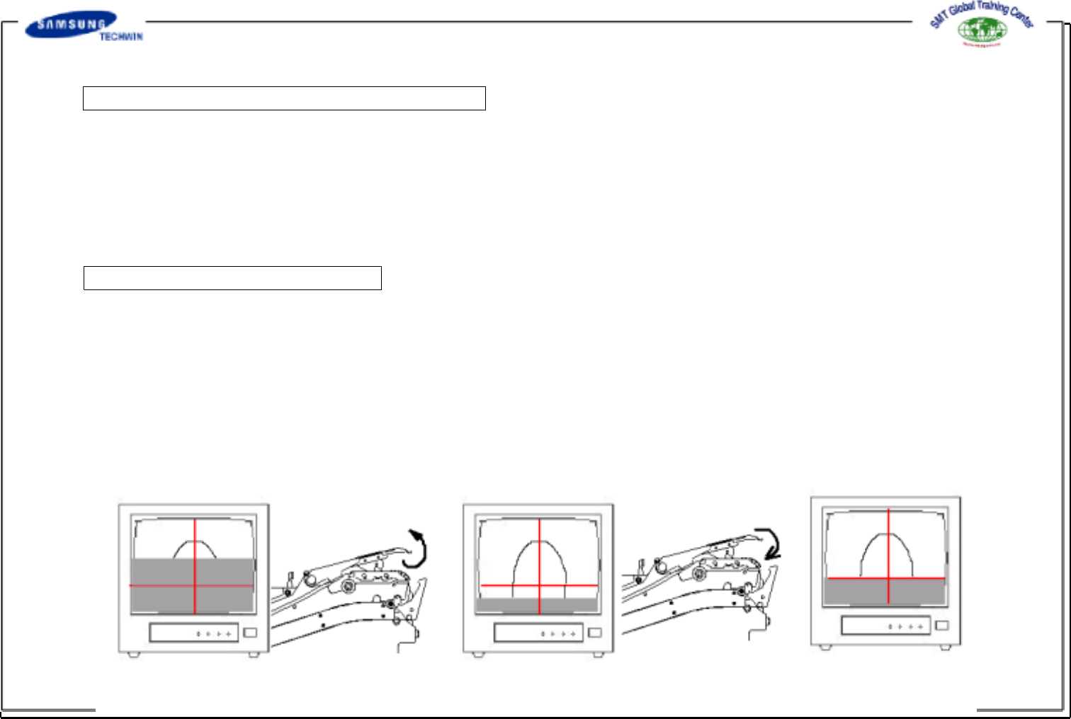
Step3 : Tape Guide Setting
If inspecting the gear on Monitor 1 whose feeder was fixed to inspection jig and set, you can see that the
reference line of the tape guide cover was changed upward or downward as shown in
the following figures.
Then, bend the ends of the tape guide cover to offset direction as shown in the following figures.
* Care is to be taken for ensuring that the center of the tape guide cover can not be bent during bending
process as shown in the following figures.